Create an Architectural Model
Create walls
From the imported plans, it’s possible to start inserting the construction elements. We will start with the insertion of walls, because elements such as doors and windows can only be inserted in a host element, in this case, walls.
Before drawing the walls, a new wall type will be created from an existing model in Revit. To do this, access the Architecture tab and click on Walls. In the Properties Palette, select the wall of the type “Basic Wall: Generic – 200mm.”
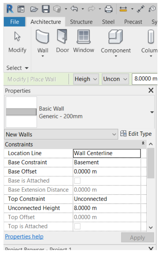
After selecting the type of wall, in the Properties Palette, click on the Edit Type button to open a Type Properties window, then click on Duplicate to create a new type of wall and the changes made do not affect the original type of wall. Define the new type with the following name: “.Ext 40cm”.
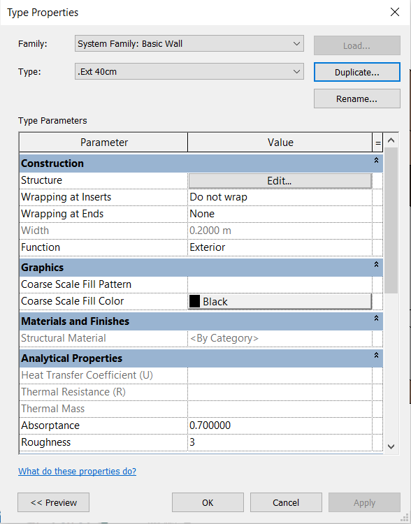
In the Function parameter, keep the setting: Exterior.
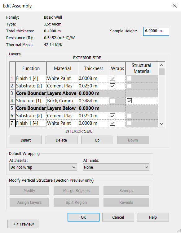
In Structure, click on Edit to open the Edit Assembly window, which serves to change the wall layers. This type of wall has only one layer, so other layers with distinct functions, materials and thicknesses will be added.
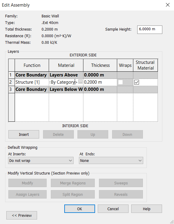
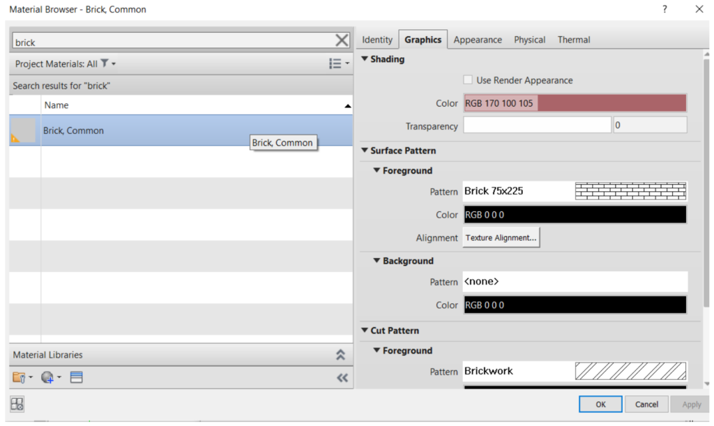
First you must change the existing layer. In Function, keep Structure [1] selected. In Materials, click on the icon  to open the Material Browser window, which will show all materials contained in the Revit library. To make the search easy, you can type the name of the material in the search bar at the top of the window. In this case, select the Brick Common material, click OK to close the Material Browser window. In Thickness, enter the value of 0.35 m for this layer.
To insert a new layer, click on Insert. It´s possible to move layers to the inner side or the outer side by clicking Up or Down.
Insert four new layers, two with the Substrate function and with a thickness of 0.025 m and another two with the Finish function, and with a thickness of 0.0008m, which is the minimum thickness accepted by Revit. Another option is to place the paint layer with the Membrane Layer function, in which you can enter 0.00 m for the thickness. The materials of these layers will be added next.
Due to the input of the value for the Finish layer, the Total thickness of the wall will be 0.4016 m. For more accurate measurements, the Structure layer thickness will be changed to 0.3484 m so that the total thickness is exactly 0,40 m.
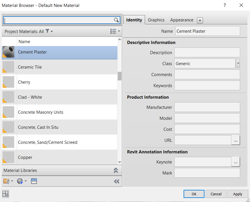
Now the materials of these created layers will be inserted. By clicking on the icon  and searching for “plaster” or “paint” materials, these are not found in the Revit library, it is possible to create new materials. By clicking on the Creates and Duplicates Materials
 ![]() , a new material will be created with the name “Default New Material” which can be renamed in the Identity tab, under Name. Rename “Cement Plaster”.
, a new material will be created with the name “Default New Material” which can be renamed in the Identity tab, under Name. Rename “Cement Plaster”.
With the new material selected, it’s possible to search for pre-defined materials to link, by clicking on the Opens/Closes asset browser ![]() . When opening the Asset Browser window, to help the search, you can type the name of the material in the search bar. When typing Plaster, the material “Cement Plaster” appears.
. When opening the Asset Browser window, to help the search, you can type the name of the material in the search bar. When typing Plaster, the material “Cement Plaster” appears.
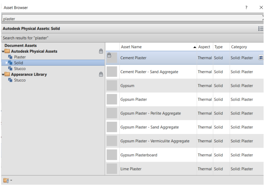
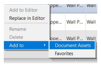
Right-click and select the Add to > Document Assets option to link this asset to the newly created asset.
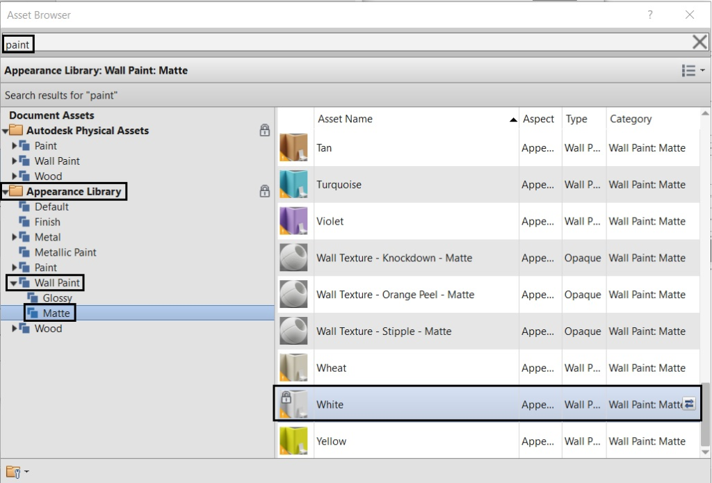
For the Finish layer, follow the same procedure: create a new material, rename the material to “White Paint”, click on the Opens/Closes asset browser ![]() , in the Asset Browser window search for ”Paint”, and finally select the “White” (Appearance Library:Wall Paint:Matte).
, in the Asset Browser window search for ”Paint”, and finally select the “White” (Appearance Library:Wall Paint:Matte).
When finishing the insertion of layers, the wall will have the definitions of the image below. Then just click on OK and the wall will be created.

In this project there are also 0.20 m interior walls with the same materials. To create them, just select the wall type “.Ext 40cm” and click on Duplicate and name the new wall type “.Int 20cm”. Then, in the Function parameter, change to Interior. In Structure, click on Edit to open the Edit Assembly window, and the only change to be made is the thickness of the Brick layer, which will change to 0.1484m and the Total thickness is automatically updated to 0.20 m. Repeat the same process to create the wall “.Ext 20cm”.
After configuring the layer properties, it is possible to start inserting the exterior walls of the Basement floor. From the Project Browser, open the “Basement.dwg” view, which was created earlier, to insert this floor plan that was imported in .dwg format.
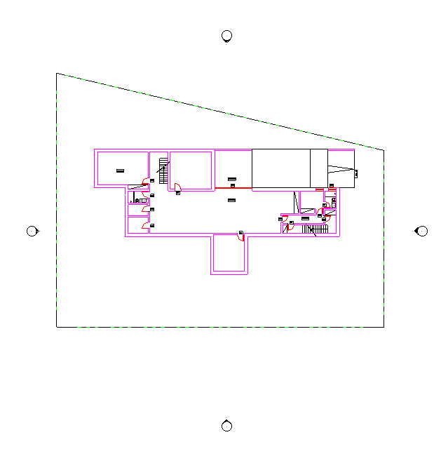
In the Architecture tab, to enable the wall insertion tool, just select Wall, or, on the keyboard, type the command “WA” (without pressing the enter key), then choose the type of wall. In Properties select the wall “.Ext 40cm”.
It is necessary to define the parameters of the Wall Instance (height and reference line of the wall drawing).
In the Options Toolbar, in the Height parameter, change to Ground Floor (implicitly specify the height of the wall up to the Ground Floor level); in Location Line, select Finish Face: Exterior (wall alignment made by the exterior side of the wall); keep the Offset at 0.00 m. Check the Chain option to draw walls continuously.

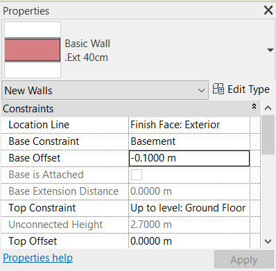
In the Properties Palette, under Base Constraint, select the Basement option, to define the reference level for the base of the walls. The negative offset to settle the walls below the Basement floor level is done in Base Offset, set the value to –0.10 m, because the walls are laid below the finishing floor that will be inserted later.
You have the option to place the walls in lines, rectangles or other shapes. In this case, keep the Line option.
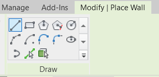
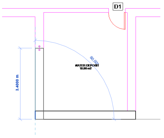
To represent the walls, zoom in as much as necessary so that you can select the outline of the walls. To invert the alignment of the interior or exterior face of the wall, simply press the spacebar before inserting it.
It is not necessary to interrupt the walls in the openings of doors and windows, because when these other elements are inserted, the opening will open automatically.
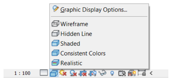
To view the inserted walls in gray, in the Visual Style icon, in the View Bar, you can select the visual of the inserted elements, by selecting Consistent Colors.
After adding all the exterior walls, in the properties window, change the wall type “.Int 20cm” and repeat the same process to insert the interior walls. Then change the type of wall to “.Ext 20cm” and insert the wall exterior (next to ramp).
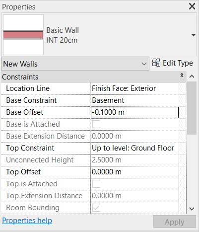
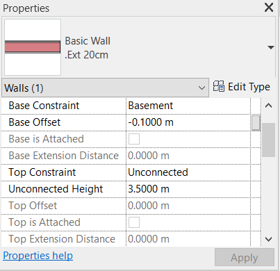
The properties of exterior wall (next to ramp) should be changed to Base Constraint: Basement; Base Offset: -0.10 m; Top Constraint: Unconnected; Unconnected Height: 3.50 m. To do so, select the wall and edit the parameters in the Properties window.
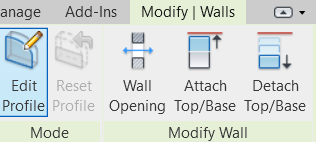
To make the exterior wall (next to ramp) inclined, you must click on it to select it. In the Modify tab, select the Edit Profile tool.
Note 1: For a better view in Profile Edit mode, it is recommended to open a section view where the wall is visible. (see how to create a section view in item 5.9.8)
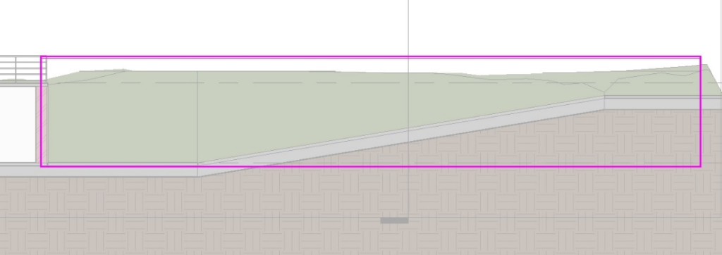
Using the Line tool ![]() , draw an inclined line at the base of the wall that meets the ramp. Trim the lines using the Trim tool, so the contour looks like this:
, draw an inclined line at the base of the wall that meets the ramp. Trim the lines using the Trim tool, so the contour looks like this:

In the Mode panel, click on Finish Edit Mode ![]() to complete it.
to complete it.

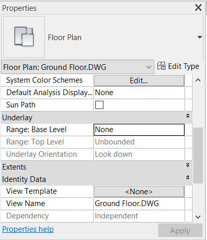
The walls drawn on the lower floor may be visible in the upper floor plan views. To change this parameter, access the properties window and in the Underlay parameter, Range: Base level, set it to None.
After inserting all the Basement level walls, repeat the entire process for the Ground Floor. To do this, open the view “GroundFloor.dwg”. For each floor you need to define the parameters of the Wall Instance, as you did for the Basement floor.
On Ground Floor, the Height parameter will be Roof, and the Base Constraint will be Ground Floor. In Location Line, select Finish Face: Exterior, keep the Offset value at 0.00 m.
Next for the Roof floor, open the Roof view because in this case none .dwg file was imported. The walls of this floor will be based on the external walls of the Ground Floor. In this case, the visualization of the walls drawn on the lower floor can be activated again.
In the Height parameter, set the Unconnected option and enter the value of 0.80 m, which will be the height of the parapet, and the Base Constraint select Roof. In Location Line, select Finish Face: Exterior, keep the Offset value at 0.00 m.

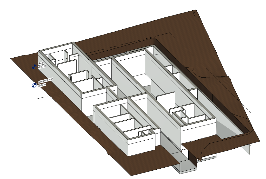
After inserting all the walls, with the Visual Style in Realistic mode and in 3D view, the model will look like the following image:
Note 2: It is possible to insert walls without being based on an imported drawing in .dwg format. For this, the process is basically the same as the one mentioned so far. The difference is that the walls will not be drawn on top of an imported plan. Just select the level where you want to insert the walls and draw them in free format, with dimensions adapted to the project in which you are working.
Note 3: At this stage, it is recommended to level the terrain, as explained in Note of item 5.8.
Place Doors
To insert the doors, go to the Architecture tab, Build panel and click on Door.

In the Object Type Selector, select the M_Single-Flush door type: 0762x2032mm.
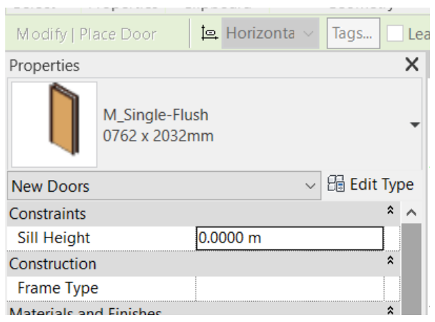
To create a door of the same family but with different dimensions, click on Edit Type, Duplicate and rename to “0.80m x 2.10m”. The Type Properties Palette will then open, where only the Height (2,10 m) and Width (0,80 m) parameters will be changed.
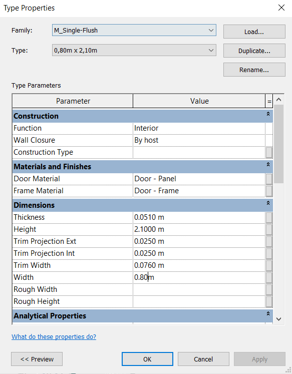
Repeat the same process for all the families and their respective dimensions that are required for the project. In this case, the doors used were:
- M_Single-Flush: 0.80 m x 2.10 m (D1)
- M_Single-Flush: 0.70 m x 2.10 m (D2)
- M_Single-Flush: 1.50 m x 2.50 m (D3)
- M_Door-Double-Sliding: 4.00 m x 2.10 m (D4)
- M_Door-Double-Sliding: 3.00 m x 2.10m (D5)
- M_Door-Double-Sliding: 2.00 m x 2.10 m (D6)
- M_Door-Garage-Flush_Panel: 4.85 m x 2.20m (D7)
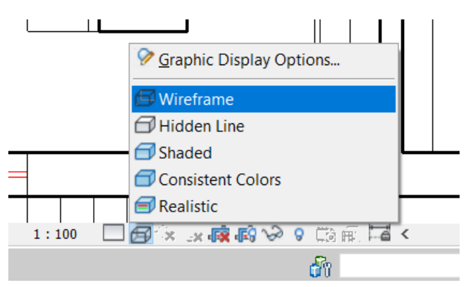
In the Drawing Area, open the view where the .dwg plan was (“Basement.dwg” or “Ground Floor.dwg”) so that you can see where the doors are located. For a better view, on the View bar select the Wireframe option, so that the walls drawn in Revit do not hide the doors and windows.
Bring the mouse to the wall where you want to insert the door. Some temporary reference dimensions appear that help to place the object, which can be edited after the object placement. Click on the wall to insert. After introducing the door, press the Esc button.
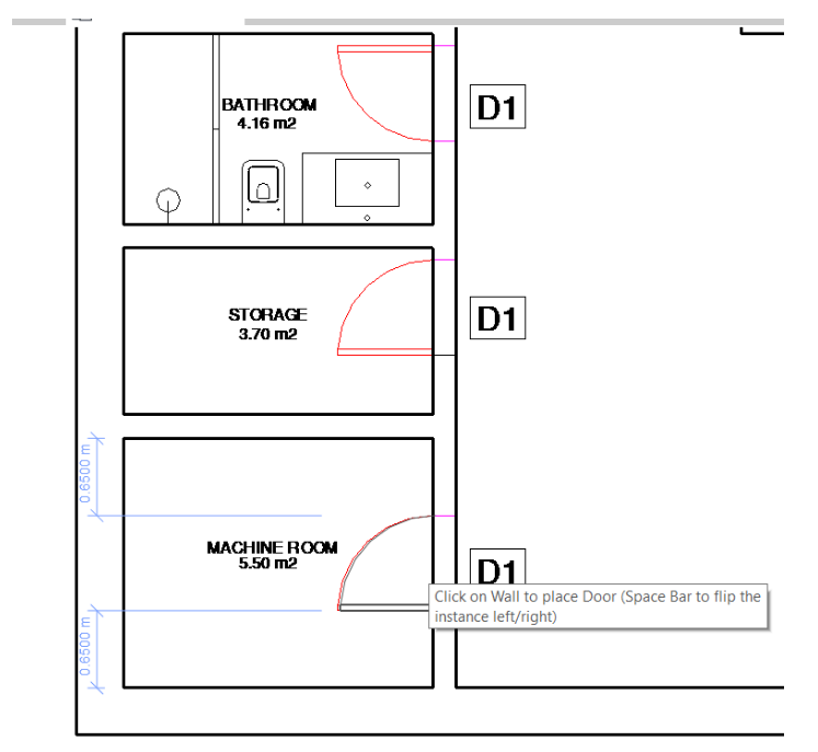
To be able to change the distances between the door and the walls, click on the door and then on the dimension value and type the new distance you want, ending up by clicking on Enter.
To invert the door’s orientation, you can click on ![]() and
and ![]() , or press the spacebar key.
, or press the spacebar key.
Place Windows
Inserting windows is basically the same as inserting doors. You must go to the Architecture tab, Build panel and click on Window.
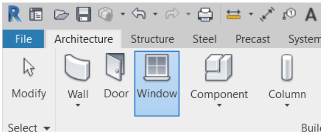
In the Object Type Selector, select the M_Fixed window type: 0406x0610mm.
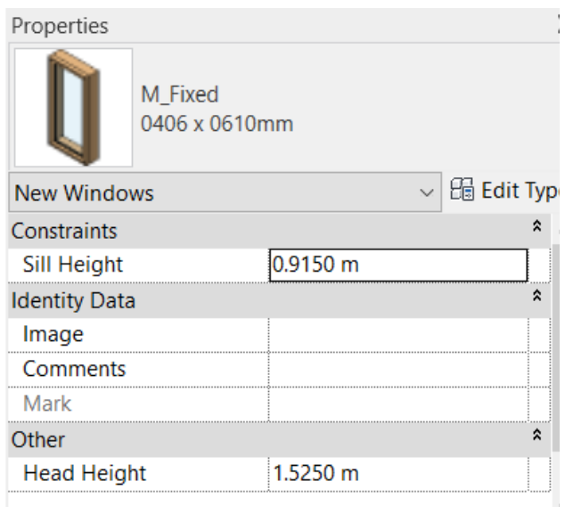
To create a window of the same family but with different dimensions, click on Edit Type, Duplicate and rename to “0.50m x 1.00m / 1.90m”. The Type Properties window will then open, where the Height (0.50 m) and Width (1.00 m) parameters will be changed, as well as the Default Sill Height (1.90 m).
Repeat the same process for all families and their respective dimensions that are required for the project. In this case, the windows used were:
- M_Fixed: 1.00m x 0.50m / 1.90m (W1)
- M_Window-Sliding-Double: 3.00m x 1.20m / 0.,90m (W2)
- M_Window-Sliding-Double: 3.90m x 1.20m / 0.90m (W3)
- M_Window-Sliding-Double: 2.50m x 1.20m / 1.00m (W5)
- M_Window-Single-Hung: 1.60m x 0.60m / 1.50m (W4)
- M_Window-Single-Hung: 1.10m x 0.60m / 1.90m (W6)
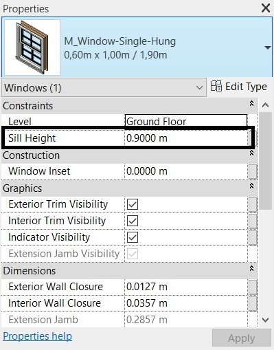
If in any family it is not possible to edit the “Default Sill Height” parameter in the Type Properties window, you must edit the Sill Height parameter in the Properties Palette with the desired value for the sill.
Create Floors
To create a floor, it is necessary to draw an outline to create the boundary. There are several ways to create boundaries for floors. In this case, the boundary outline will be drawn based on the existing walls. If a wall is moved to accommodate a design change, the floor will also automatically move with it.
The floor boundary must be a closed loop. To create an opening in the floor, it is possible to sketch another closed loop where the opening should appear.
In the Project Browser, select the Basement.dwg plan. In the Architecture Tab, Build panel, select the Floor tool.

On the Modify | Create Floor Boundary, in the Draw panel, select the Pick Walls tool, to draw the boundaries based on the existing walls.
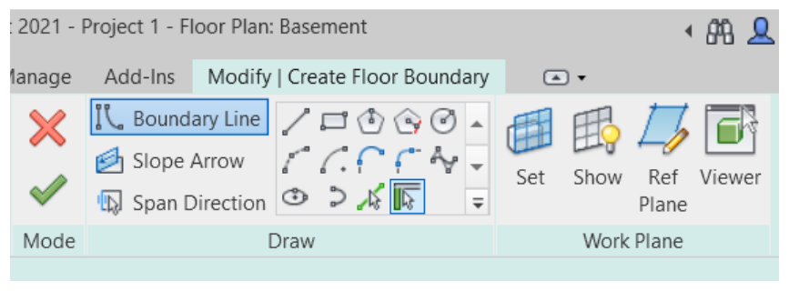
In the Options Bar, check that the option Extend into wall (to core) is selected (this option allows the slab area to be defined up to the wall core line). In the Offset field, keep 0.00 m.

Position the cursor over the walls and click on each one to place a boundary line, the alignment of the floor will be on the outside of the wall, as shown in the image.
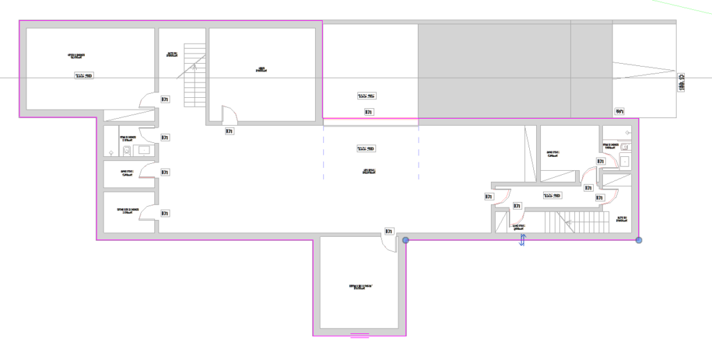
To trim the lines that exceed the boundary, access the Modify | Create Floor Boundary, and in the Modify panel select the tool Trim/Extend to Corner ![]() . Trim the corners of the boundary by selecting the lines on the sides that will be kept.
. Trim the corners of the boundary by selecting the lines on the sides that will be kept.
After drawing the outline of the floor boundaries, in the Properties Palette, select the material “Generic 150mm” and click on Edit Type to open the Type Properties window. When opening the window, click on Duplicate and rename it to “Generic 10cm”. In Structure, click on Edit to open the Edit Assembly window and change the layer thickness to 0.10 m. Keep the Function parameter as Interior.

After the boundary forms a closed loop, on the Mode panel, click on Finish Edit Mode ![]() .
.
After clicking Finish Edit Mode, the following messages may appear:

This message allows you to connect the top of the walls with the lower face of the slabs. It is suggested that you click on Don’t Attach.

This message intends that Revit subtracts the common part between the Slab and the Wall, it is suggested to answer Yes.
As with all other building elements in Revit, it is possible to set the floor parameters using the Properties Palette You can change the floor family, function (indoor/outdoor) and create new types, with layers of varied materials and thicknesses as needed for each project.
For this project, only generic floors will be used.
To insert the project’s floors, in the Basement, Ground Floor and Roof plans, you must perform the same procedure to draw the contour.
In the stairs area, create a rectangle to make an opening in the floor.

The interior floor of the Ground Floor should look similar to the following image. After the contour is bounded fully closed, in the Mode panel click Finish Edit Mode ![]() to complete the drawing.
to complete the drawing.
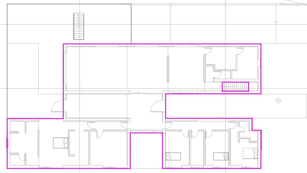
Then, to apply the exterior floors of the Ground Floor, in the Properties window, duplicate the created floor and create a new one, just changing the Function parameter to Exterior to be used on the balconies on the Ground Floor.
As the floor boundary must be a closed circuit, to place all the exterior floors, they must be created separately, as shown in the following images.
Balcony floor, using the Line tool:
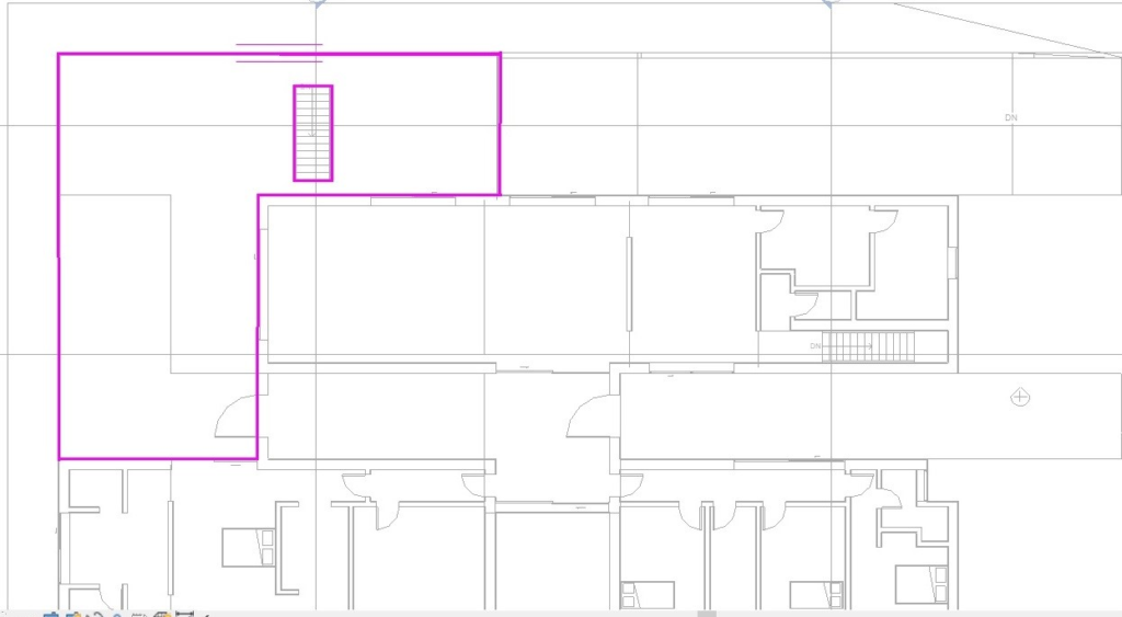
Access floor, using the Rectangle tool:

Ramp access floor, using the Rectangle tool:

Create Stairs and Railings
To create stairs, access the view which will be the base of the stairway. In this case, open the Basement.dwg floor plan.
After opening the plan, in the Architecture tab, Circulation panel, select the Stairs icon.

In the Properties Palette, under Constraints, set on Base Level: Basement, and on Top Level: Ground Floor.
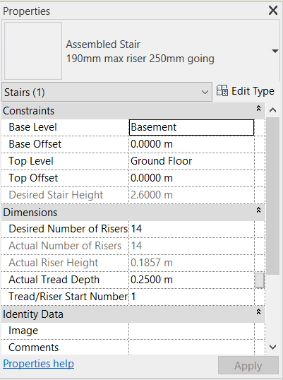
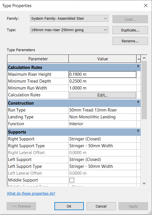
In this case, other stairs properties will not be changed, but it is possible to change many other parameters by clicking on Edit Type, even the calculation rules (Calculation Rules).
In the Options bar, set the location line to Run: Center.

In the Basement plan, zoom in so that the stairs is visible and click on the center of the base step to start running the stairs. Move the cursor to the end of the stairs and click on the center of the last step.
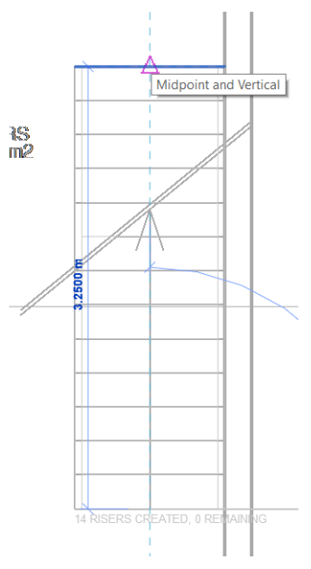
In the Mode panel, click on Finish Edit Mode ![]() to complete.
to complete.
The stairs will be created, and to better visualize the stairway in the 3D View, after selecting the stairs, just click on the Selection Box ![]() in the View panel of the Modify Tab | Stairs.
in the View panel of the Modify Tab | Stairs.
A 3D view will open with a cutout of only the selected stairs, and it is possible to see that the railings were inserted automatically. To edit a railing, just click to select it.
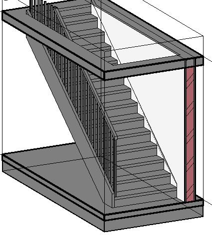
In the Properties Palette it is possible to edit the type of handrail and its dimensions. In this case, the railings on the side of the wall will be removed by selecting the element and press up the delete key.
To return to the 3D view of the entire project, just select the Section Box clicking on one of its edges, and in the Properties Palette, deselect the Section Box option.

Repeat the same process for all the stairs in the project.
It is possible to insert railings without being linked to a stairway, for example, on balconies. To do this, access the Architecture tab, Circulation panel and select the Railing tool.
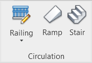
On the Modify | Create Railing Path, in the Draw panel, select the Line tool to draw the railing, double-clicking at the end of each line to make a continuous line.

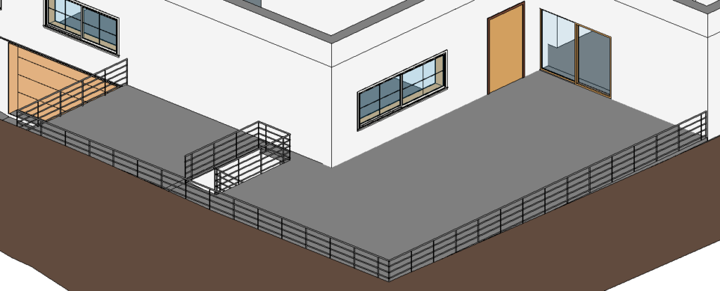
Draw the lines where the railing is to be inserted.

In the Properties Palette, change the railing type to “900mm Pipe”, so that it looks like the image below.
Create Ramp
The easiest way to insert a ramp is by sketching a section with the Run tool, like creating stairs.
First, open one of the plans in which the ramp of the imported file in .dwg format is visible (Basement.dwg or Ground Floor.dwg).
Click on the Architecture tab, Circulation panel and select the Ramp tool.

Open the Modify tab | Create Ramp Sketch, in the Draw panel select the Line tool.
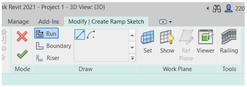
After selecting the Line tool, move the cursor towards the drawing area and click on the base and top of the ramp to sketch the section.
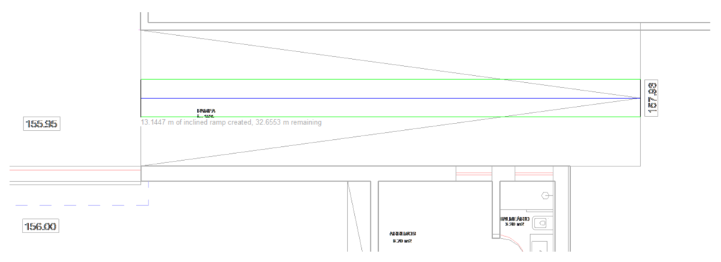
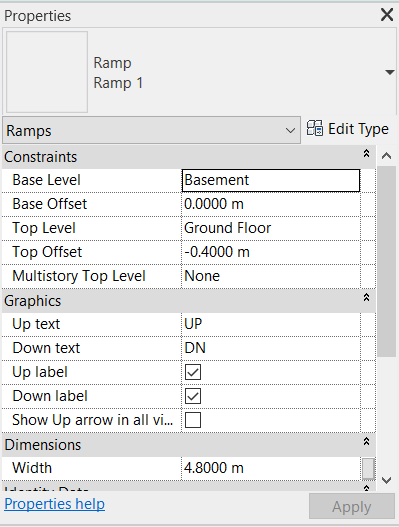
In the Properties Palette set:
- Base Level: Basement
- Base Offset: 0.00 m (offset below Basement floor)
- Top Level: Ground Floor
- Top Offset: -0.40 m (offset below Ground Floor)
- Width: 4.80 m
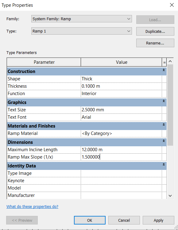
Click on Edit Type and change the Thickness to 0.10m and Ramp Max Slope parameter to 1.5 (15% slope).
In the Mode panel, click on Finish Edit Mode ![]() to complete.
to complete.
Note: If when defining the length of the ramp with the Line command, it does not assume the true length, edit it by clicking on the line and dragging it to the end of the ramp.


If the ramp is inserted with railings, just select it and press the delete key to remove it.
The appearance of the ramp should look similar to the image below:

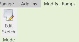
If it is necessary to edit the ramp, it must be selected and in the Modify | Ramps, click on the Edit Sketch tool.
Create Roof
From the Project Browser, access the Roof floor plan. In the Architecture tab, Build panel, Roof tool – by Footprint.
In the Modify | Create Roof Footprint, Draw panel, select the Rectangle or Line tool to draw the outline of the roof boundary.

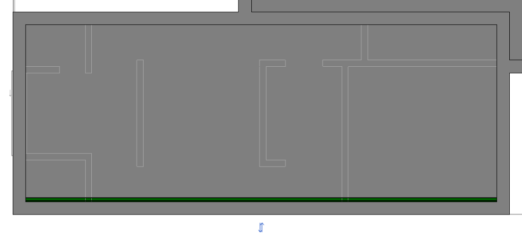
Using the Rectangle tool, draw a rectangle by clicking on the interior face of the walls. Select the inferior line and move it 0.125 meters in relation to the wall, to leave space for the gutter, so that it looks like the figure below.
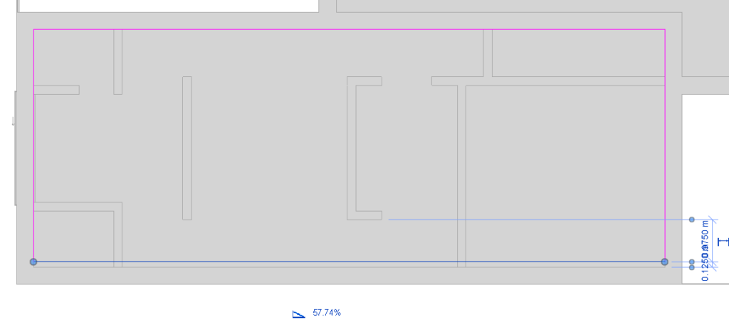
Select the line that was moved, and in the Options Bar, check the Defines Slope option. Uncheck this option for the other lines, as the roof will only fall to one side.

With the line that was moved selected, in the Properties window, in the Slope parameter, set it to 10%. In the Mode panel, click the Finish Edit Mode icon to complete.
The type of roof that will be used will be Basic Roof / Generic – 125mm.
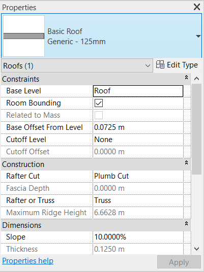
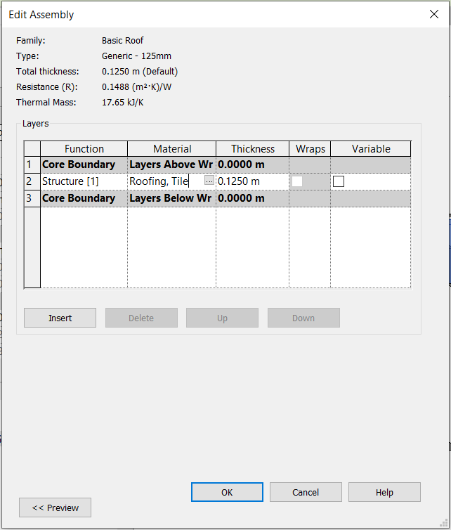
Click on Edit Type to open the Type Properties window. In the Structure parameter, click on Edit to open the Edit Assembly window. In the Material column, click on the icon with three dots to open the Material Browser window. In the search bar, look for the material “Roofing, Tile” and select it.
In the Mode panel, click on Finish Edit Mode ![]() to complete.
to complete.
To insert the gutter, access the Architecture tab, Roof tool and select the Roof: Gutter option.
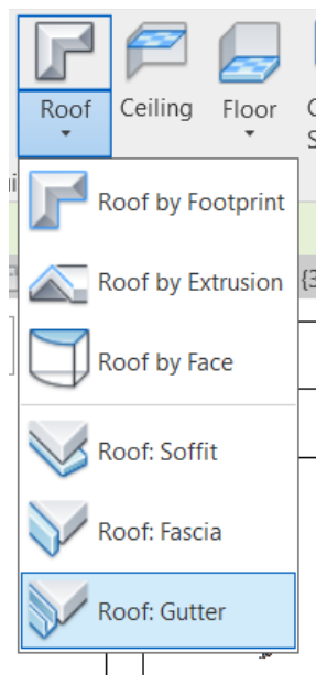
After selecting the tool, just click on the roof line where the gutter should be inserted. It is not necessary to edit any parameters of the gutter, it will adjust to the available space that was left previously (0.125 m).
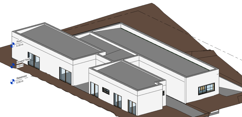
Repeat the same process for the other areas of the coverage, so that the roofs are like the image below:
Create Section Views
Creating sections views is very simple. In the Project Browser, select the plan of one of the floors.
In the View tab, Create panel, select the Section tool.

Move the cursor to the plan and click on a point outside the boundary of the walls. After clicking on the first point, pass the line over the design and click on another point on the opposite side so that the section is created.
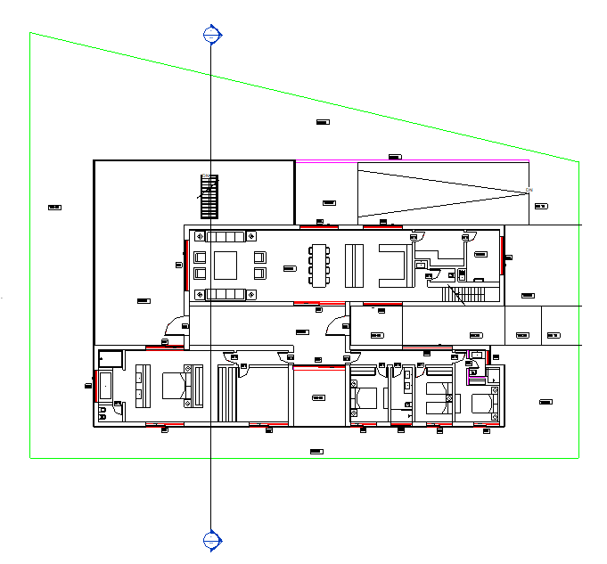
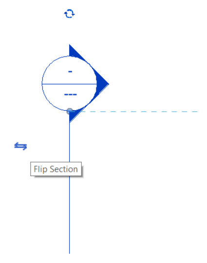
To invert the section, just click on the Flip Section icon.
To open the section view, just double click on the section header symbol. You can also open the view from the Project Browser, where a view is automatically created for each section.
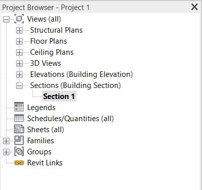
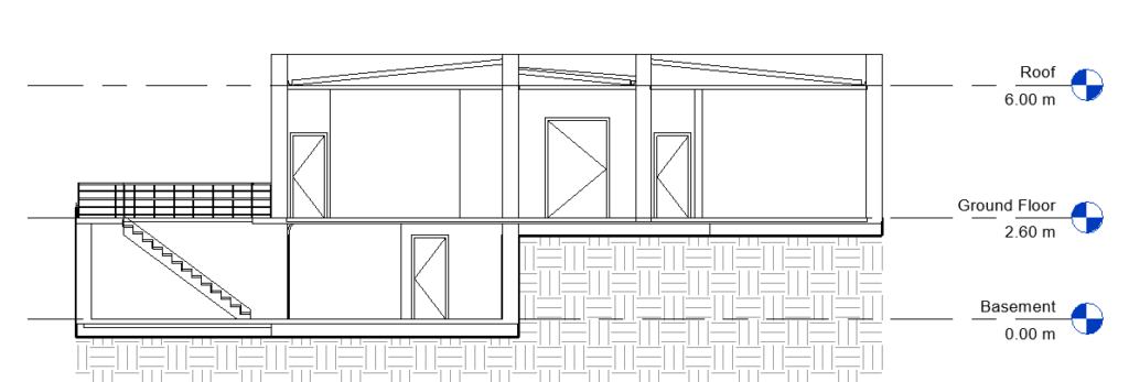
When you open the section, the floor levels also appear.
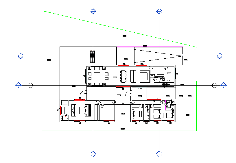
It is possible to create several sections. For this project, four sections were created, as shown in the following image:
Join Elements
There is a tool that joins or separates object geometries. For example, in this project there are lines joining the walls of different floors, but these lines do not make sense as they are the same materials.
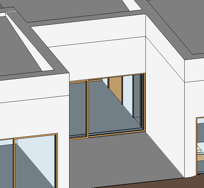
To access this tool, open the Modify tab and select Join Geometry.
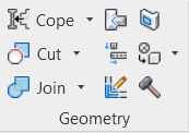
If you want several objects to be joined, in the Options Bar, select the Multiple Join option.

After selecting the tool, click on the elements that you want to join. The result will be as in the image below:
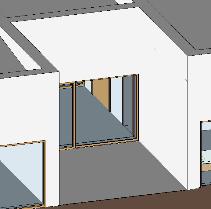
This tool should be used whenever necessary, to join walls, floors and other elements. It is also recommended to see in the Section views if there are elements to be joined.
However, in some cases, this tool doesn’t work, so a small analysis of the design and manual adjustment is necessary.
Components: Furniture
Revit allows you to insert more components such as furniture and garden elements. To insert them, access the Architecture tab, Build panel and click Component, Place a Component.

In the Properties Palette, you can choose the type of element you want to insert.
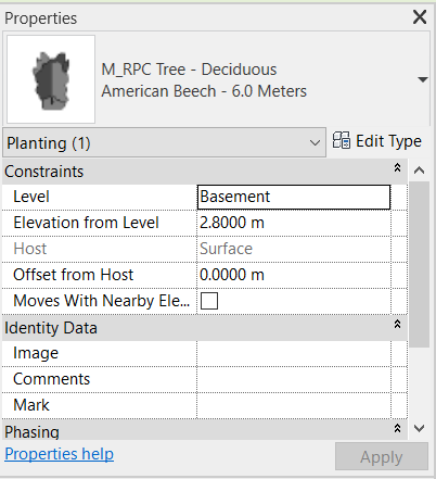
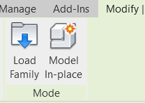
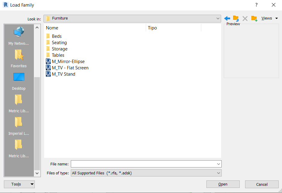
By clicking on Load Family, in the Modify tab, it is possible to load more components from the Revit library according to each user’s preference, as was done for the doors and windows previously.
In the Furniture folder, there are several types of objects that can be inserted in a project. For example, a Bed family will be loaded.
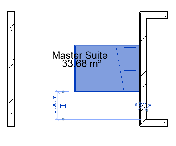
To be able to rotate objects in a certain orientation, just bring the object to be introduced close to another object (wall, line, …) and click on the keyboard’s Spacebar.
