Annotations
Revit provides several annotation tools to insert into projects. Next, the way to use some of these tools, such as: room name and area, dimensions, floor dimensions, texts, detail lines will be shown.
It is important to note that annotations are placed in the view where they were created and are not visible in any other view.
Room Tags
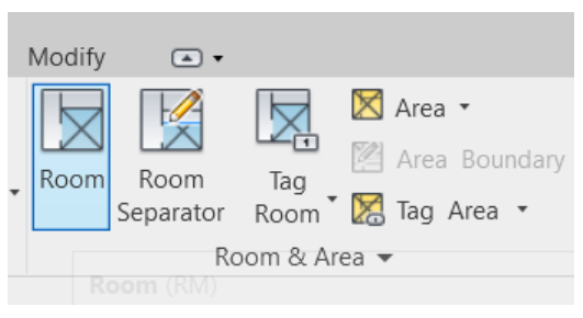
Revit has a tool to enter the names of rooms and their respective areas. With the view of one of the plans open, access the Architecture tab, in the Room & Area panel, and select the Room tool.
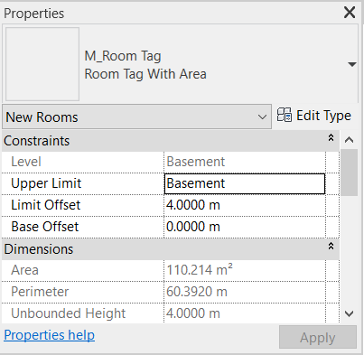
In the Properties Palette select the “Room Tag With Area” family.
When you bring the mouse close to an environment enclosed by walls, Revit automatically recognizes the space and calculates the area. Click on the environment to enter the text.
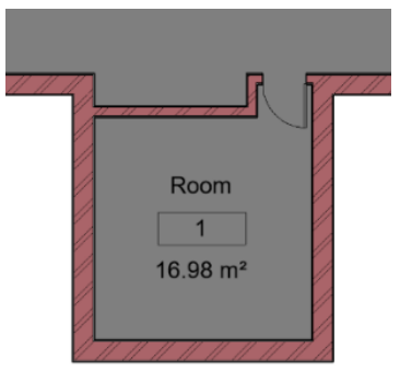
To edit the environment name, just double click on its title and rename it.
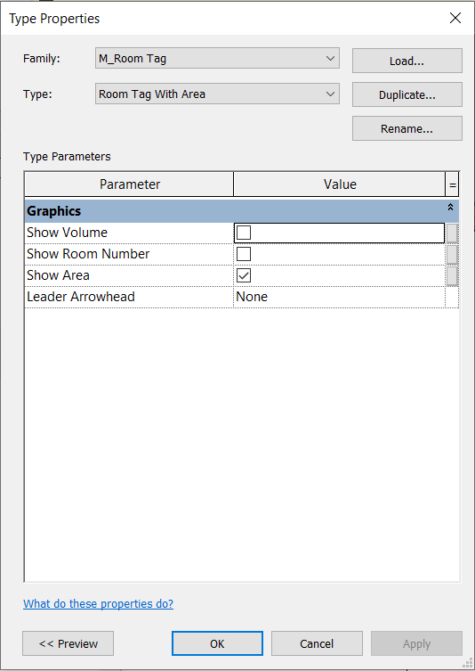
To delete room numbering, access the Properties Palette, click Edit Type, and in the Type Properties window, uncheck the option “Show Room Number”.
When deleting the room numbering, a very large space is kept between the Name and Area text.
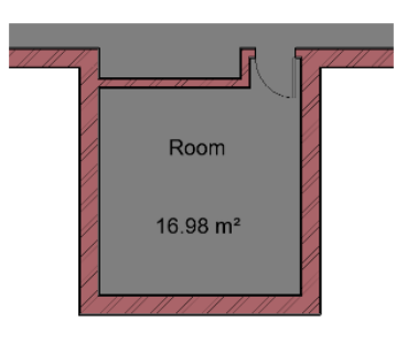
To remove this space, it is necessary to edit this tag’s family. To do this, double-click on the text in the area, and a new tab will open for editing. You must remove the text box with the number and volume and drag the text box from the area closer to the name of the environment, so that it looks like the one shown in the image below.
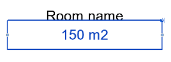
To apply this edition, click on the Load into Project icon.

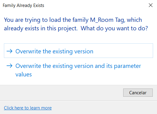
Select the option “Overwrite the existing version”
In rooms that are not closed off by walls on all sides, for example in the Living Room, Dining Room and Kitchen, it is necessary to create an Environment Separator. To do this, access the Architecture tab, Room & Area panel, and select the Room Separator tool.
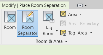
This tool allows you to draw lines to delimit the area of the rooms. In the example in the image below, lines have been drawn to separate the Living Room, Dining Room and Kitchen.
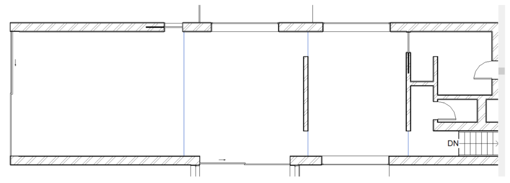
After inserting the separators, you can use the Room tool normally as in a closed room.
Based on the above instructions, name all the environments according to the plans of the files in .dwg format.
Text
There is also the possibility to add texts without adding an environment. To do this, access the Annotate tab, Text panel and select the Text tool.

To add only one free text box, select the first option “No Leader” or select options with indicative arrows, which can be: one segment, two segments or curved.
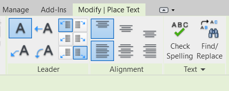
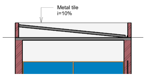
This tool is useful for naming some project specifications, such as materials:
Dimensions
To insert the dimensions in the project, you can access the Align Dimension tool, in the Quick Access Toolbar.

In the Options Bar, select the options “Wall faces” and “Individual Reference”.

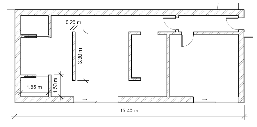
To insert the dimensions in the plans, click on the face of the wall where the dimension will start, then on the face of the wall where it will end, and finally drag the dimension to the wanted position and click to position it.
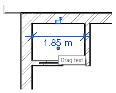
It is possible to only move the dimension text. To do this, click on the circle below the text and drag it to the desired position.
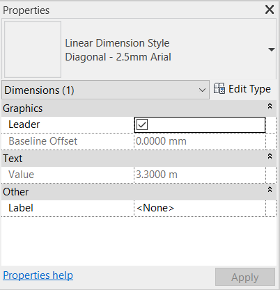
You can change the style of the representation (lines, symbols and font). In this case, the default configuration for the “Diagonal – 2.5mm Arial” type will be maintained.
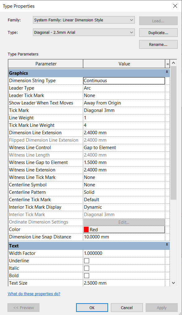
To make changes, if necessary, click Edit Type to open the Type Properties window. This window shows several parameters that can be changed, such as: tick mark, color, size and font of the text. In this case, only the parameter Color was changed to Red.
In the same way, you can insert dimensions in section views.
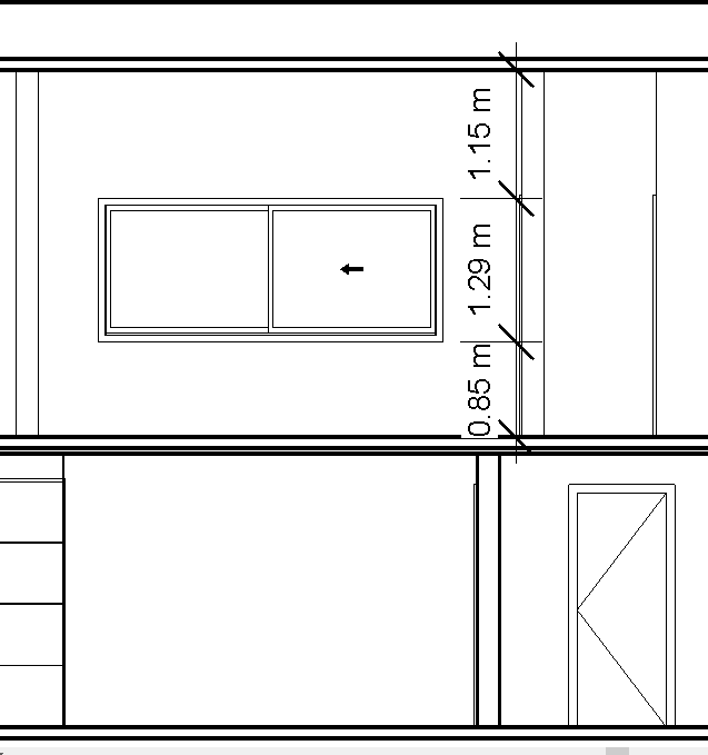
Spot Elevation
It is possible to define and represent the floor dimensions in different views, either in plan views or in section and elevation views.
To start, open the view in which you want to insert the floor dimensions. In this case, open the Basement plant.
Access the Annotate tab, Dimension panel and click on Spot Elevation.

In the Properties window, select the Spot Elevations: Target (Project) option.
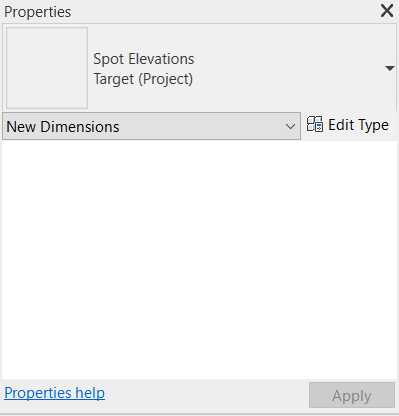
In the Options Bar, remove the Leader option.

Click on the place where you want the object to be introduced. Proceed in the same way to insert all objects, in the Basement and Ground Floor plans.
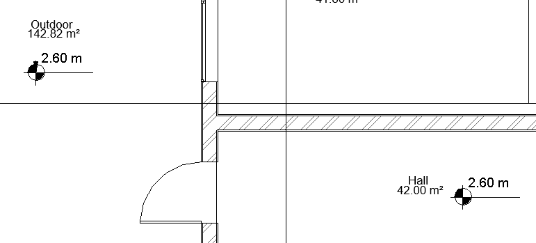
To insert altimetric dimensions in the sections (or any other view of the model), the procedure is the same.
Tags
It is possible to insert tags that identify the introduced objects. These tags have a parametric link with the objects they refer to. , That is to say, if the object is moved, the tag is also automatically moved in the same way that, if the object is removed, the tag will also be.
To insert the tags, with one of the plans open (Basement or Ground Floor), access the Annotate tab, Tag panel and select the Tag All tool.

A window will open to select the categories of elements in which the tags will be added. For this project, select only the “Door Tags” and “Window Tags” options.

After clicking on OK, it can be seen that labels have been inserted in all elements of the view (perform the same process for Basement and Ground Floor views).
Inserted tags are automatically numbered in the order in which the elements were added to the project. For reasons of organization, all doors or windows of the same type should be identified by an identical label.
To edit this parameter, click on one of the labels and in the Modify tab, click on the Edit Family icon.
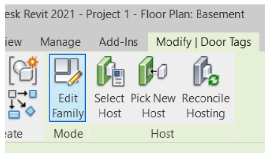
A window for editing the family will open. The value 101 is a representative value; it serves to confirm the size and color of the text.
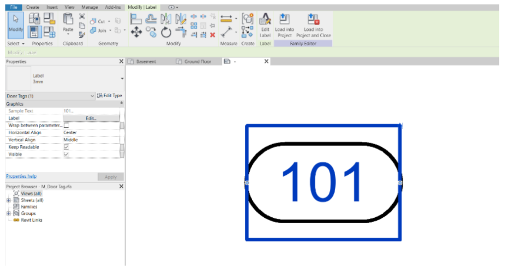
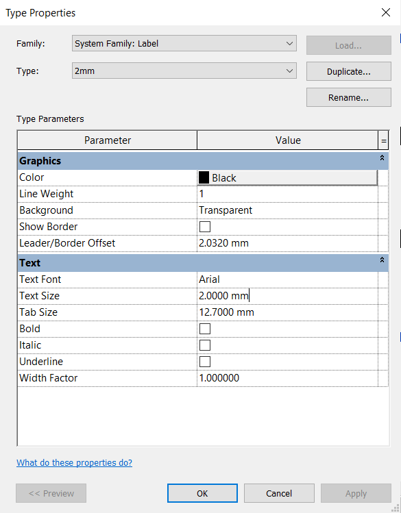
To change the text size, click on Edit Type to open the Type Properties window. In this window, click on Duplicate and rename to “2mm”. In the Text Size parameter, change the value to 2.00 mm and click on OK.
What is also intended to change is that the information provided for the label is the parameter that identifies the type of port. To do this, select the text and click on Edit Label in the Modify panel.

When opening the Edit Label window, in the Category Parameters column, select Type Mark and click on Add parameter to label.
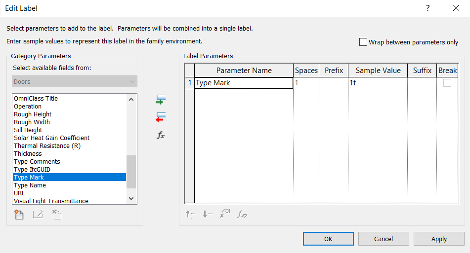
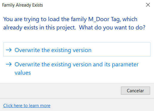
After clicking on OK, in the Family Editor panel, click on the Load into Project icon.
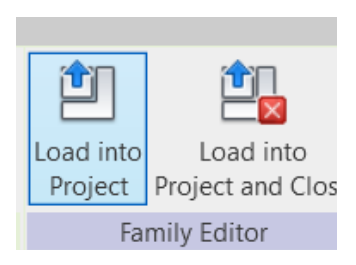
The window with the warning, Family Already Exists, will appear, select the option “Overwrite the existing version”.
Automatically all door and window labels that are of the same type will have the same numbering. To rename it just click on their text.
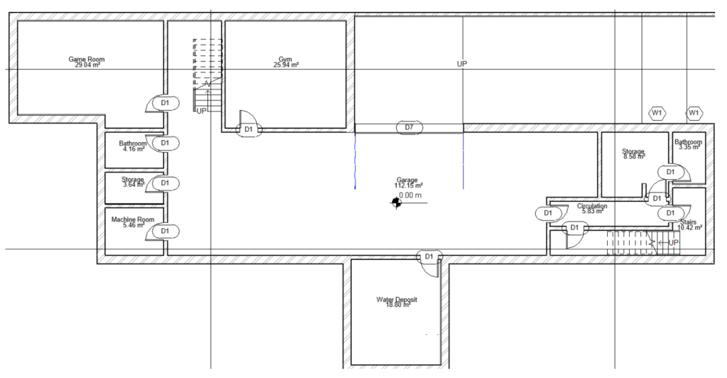
For example, a door label of 0.80m x 2.10m was renamed to “D1” and automatically all the doors of this dimension had their labels renamed with the same text.

Once the labels are configured, all doors must be renamed with the prefix “D” and the windows with the prefix “W”, followed by their respective numbering (see .dwg file to verify the numbering of doors and windows). Perform the same procedure for Basement and Ground Floor plans.
After everything has been changed, the result will be as shown in the image below:
Detail Lines
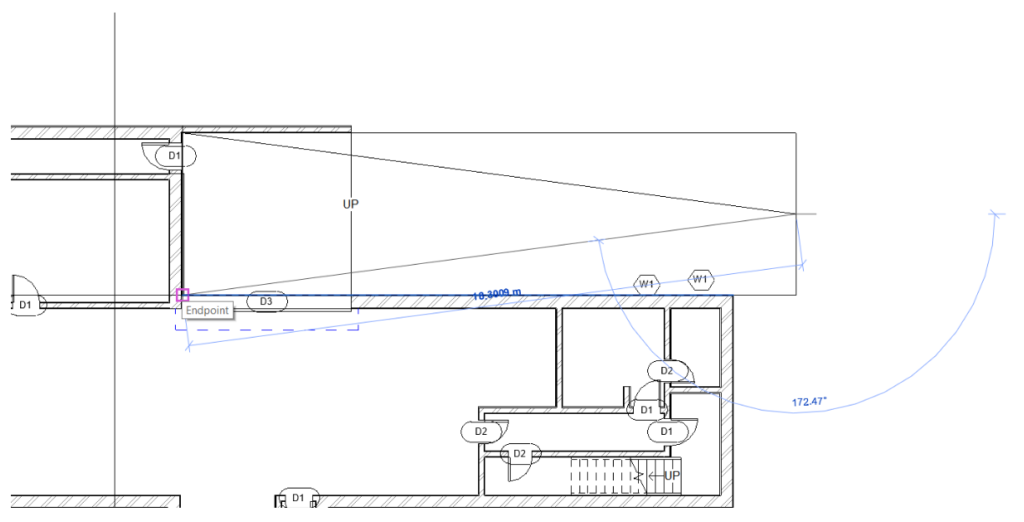
Revit allows you to draw detail lines, which serve to represent some elements, such as the slope of the ramp.
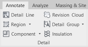
To use this tool, you need to access the Annotate tab, Detail panel and select the Detail Line tool.
With the Line tool, draw the representation of the ramp as in the image below. Press the Esc key to exit edit mode.
