Building Pads
It is possible to add a building pad to a toposurface and then modify the pad’s structure and depth.
The pad for the Basement floor will be inserted first. Open the Basement view and change the view to Wireframe (this allows you to see the imported .dwg). In the Massing & Site tab, Model Site panel, click BuildingPad.
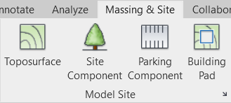
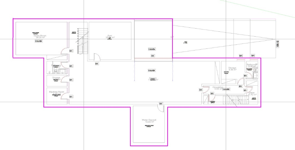
With the Line tool, trace the perimeter of the entire basement layout (except the ramp that will be added separately). The lines must form a closed perimeter without crossing each other.
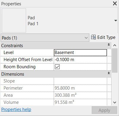
Before finishing editing the object, you need to define some properties. In the Properties Palette, in the Level parameter select Basement; this means that the pad will be associated with the level of that floor. In the Height Offset from Level parameter, introduce the value –0.10 m (this determines that the slab will be introduced 0.10 m below the Basement floor level) space to later place the finishing slab (Floor).
Click on Edit Type to open the Type Properties window. In the Structure parameter click on Edit to edit the Structure layer thickness to 0,35 m. No new layers will be added for this element.
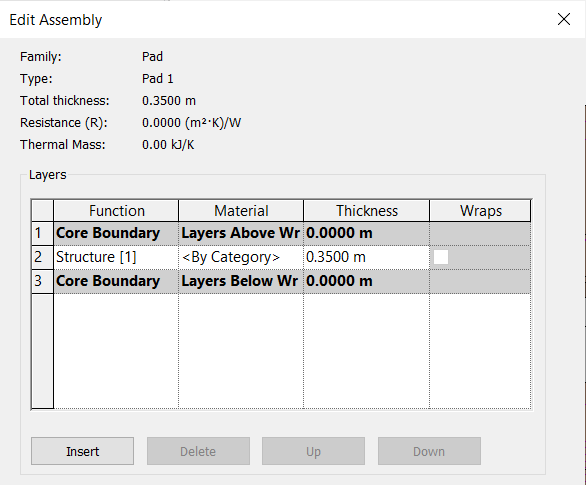
After defining the thickness, click on OK until you return to the Drawing Area. Having defined all the necessary parameters, click on Finish Edit Mode ![]() .
.
In the 3D view, the result of creating the Basement floor pad looks like the image below:
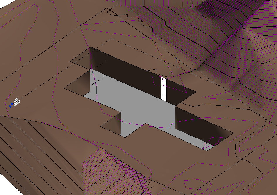
Now to create the pad for the Ground Floor level, you must open the view “Ground Floor.dwg”. In the same way as for the lower floor, access the Massing & Site tab, Model Site panel, click on BuildingPad. With the Line tool, trace the perimeter of the entire implementation of the Ground Floor (except the ramp and the access that will be added separately). The lines must form a closed perimeter without crossing each other.
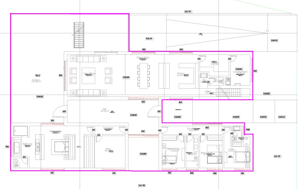
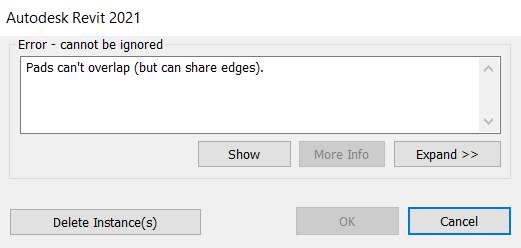
When clicking on Finish Edit Mode, an error window will appear. The error occurs due to overlapping pads, that is to say you cannot create the pad on the Ground Floor level on top of where there is already a pad on the Basement level. Click on Cancel to return to the edit mode.
To correct the error, open the “Basement.dwg” view. Since you are still in edit mode, the perimeter outline made in the “Ground Floor.dwg” view is still visible.
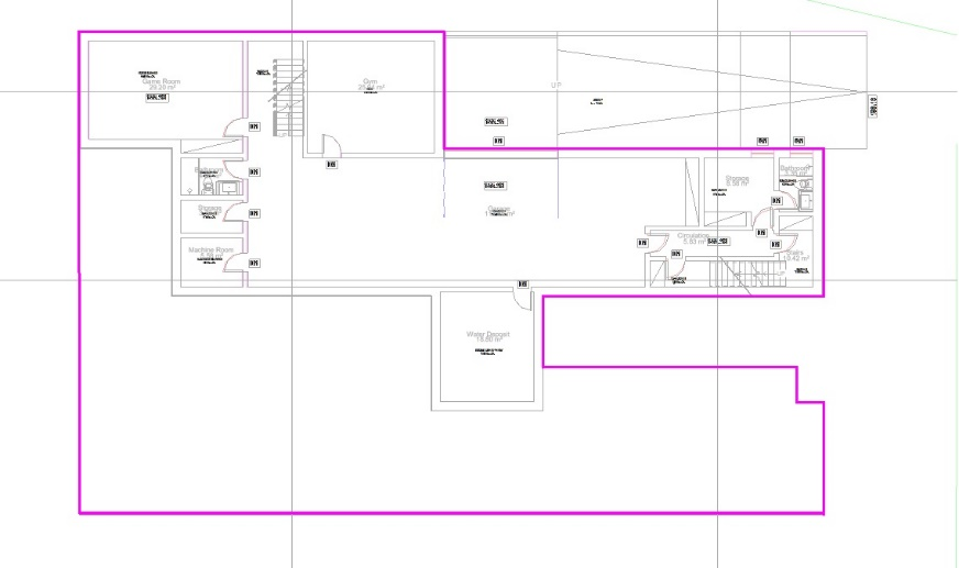
Now, with the Line tool, you must change the contour making the lines pass only outside the Basement floor implantation. It is necessary to delete the lines that overlap the Basement level, so that it looks like the following image:
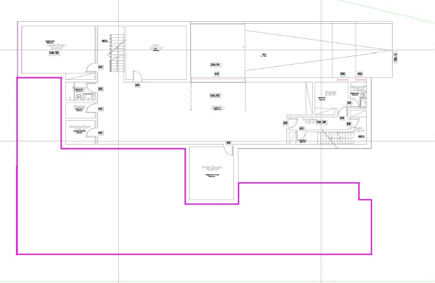
After defining the thickness of 0.35 m and in the Height Offset from Level parameter, enter the value –0.10 m, click on OK until you return to the Design Area and then on Finish Edit Mode ![]() .
.
In the 3D view, the result of creating the Ground Floor pad looks like the image below:
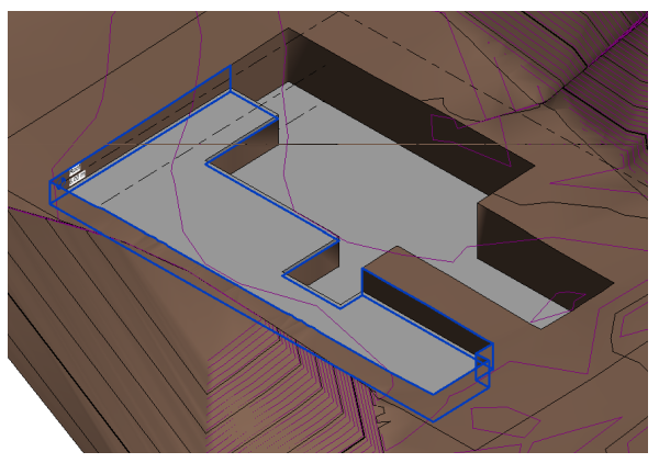
Now a pad will be added at the entrance to the residence. You can use the Rectangle tool ![]() to delimit the outline. Edit the Height Offset from Level parameter to –0.20 m from the Ground Floor.
to delimit the outline. Edit the Height Offset from Level parameter to –0.20 m from the Ground Floor.

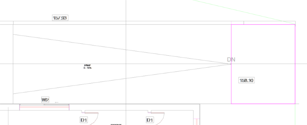
In the ramp access, a rectangular pad will also be inserted. You can use the Rectangle tool to![]() delimit the outline. Edit the Height Offset from Level parameter to -0.50 m relative to the Ground Floor.
delimit the outline. Edit the Height Offset from Level parameter to -0.50 m relative to the Ground Floor.
To create the ramp pad, open the “Basement.dwg” view. On the Massing & Site tab, Model Site panel, click BuildingPad. With the Line tool ![]() , trace the perimeter of the entire ramp.
, trace the perimeter of the entire ramp.
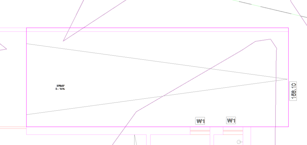
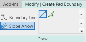
On the Modify | Create Pad Boundary, select the Slope Arrow tool.
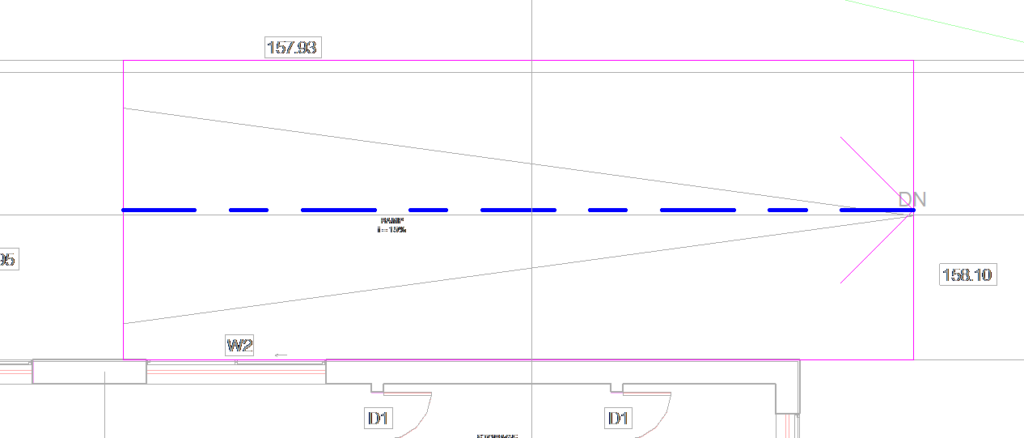
Insert the arrow in the middle of the ramp, as in the image below.
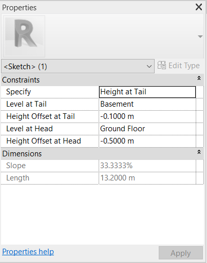
Select the arrow and in the Properties Palette, in the Specify parameter, the Height at Tail option will be kept. In Level at Tail, set Basement and the Height Offset at Tail value will be –0.10m. In Level at Head, the level will be the Ground Floor, with the Height Offset at Head parameter of –0.50 m.
If you intend to change the perimeter of any pad, you must select the object and click on the Edit Boundary button in the Modify tab. If you just want to change the Type or Instance parameters, select the object and access the Properties Palette (no need to edit the object).
- Note: Differences in elevation between the pads and the terrain can be corrected by introducing new points on the topographical surface with the desired dimensions or changing the dimensions of existing points. It is recommended to make these adjustments only after inserting the walls so that the changes in points are easily visible
In this project, the terrain overlaps some elements at the Ground Floor level, so it is recommended to add points in the areas highlighted in yellow in the image below.
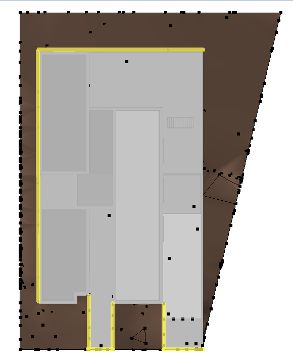
At the top of the ramp, the points must have an elevation of 2.20 m, on the perimeter of the entrance floor an elevation of 2.50 m, and on the side and back, also 2.50 m. Next, there will be an explanation of how to add points and change elevations.
To add new points, click on the terrain and in the Modify tab, click on Edit Surface.
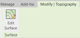
Then select the Place Point tool.
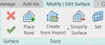
In the options bar, select the Relative to Surface option and keep the Elevation field with the value of 0.00 m.

Bring the mouse cursor to the surface of the land and click on the place where you want to insert the point.
To change the elevation of the point, click on it and in the Properties Palette enter the desired value for the Elevation parameter.
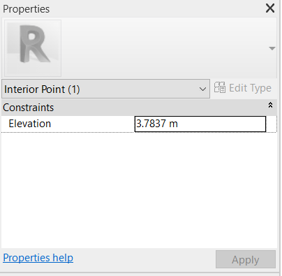
Click on Apply and visualize in the 3D view if the result obtained was what you intended or if you need to add more points or edit the elevation of the point again.
