Create a Terrain Model
Revit offers more than one way to model the topographical surface The simplest is to import a file in .dwg format that contains a survey with the contour lines in 3D.
To import the file with the contour lines, it is important that it is at the same scale and coordinates in Revit.
The contour lines will be imported into the Site view, which must be opened via the Project Browser.
In the Insert tab, select an Import CAD option.

Then a window appears to select the file to be imported, and it is possible to define all the parameters available for the import. Select Elevation.dwg file with just one click.

In the import options, check that the Current view only option is not selected, so that the file is introduced in 3D (visible in all views). In the Layers field choose the option All (all layers of the file are imported). In Import units, choose the Meters option.
In Positioning, select the Auto – Origin to Internal Origin option, making the DWG reference point the origin of the point with 0,0,0 coordinates of Revit.
The Correct lines that are slightly off the axis option allows you to automatically correct lines that are slightly slanted (less than 0.1 degree).
After defining all parameters, click on Open to load the file. The green contour line represents the terrain boundaries.

It is necessary to verify that the floor plans that have already been inserted in the project (Basement and Ground Floor) are aligned with the level curves file. (image)

If they are not aligned, just click on the terrain and with the Move tool select one of the ends of the green outline and drag until you find the corresponding end of the plan.
After importing the contour lines and aligning them with the other drawings, it is necessary to define the topographical surface. With the Site view open, access the Massing & Site tab, Model Site panel and click Toposurface.

In the Modify tab | Edit Surface, in the Tools panel, click on Create from Import>Select Import Instance and then select the drawing in the view.

Select the layers that will be used to create the Toposurface. In this case, the Curves layer.

After clicking on OK, a grid of points is generated. If a point is selected, in the Options Bar, the value of its elevation appears, which can be changed.

To finish creating the surface, on the Modify | Edit Surface tab, Surface panel, click Finish Surface ![]() .
.
In order to better visualize the topographical surface, you can create a 3D view. Click the button ![]() on the Quick Access Bar and a new view will be created in the Project Browser called {3D}. To improve the view even more, in the View Bar, change the view to Shaded.
on the Quick Access Bar and a new view will be created in the Project Browser called {3D}. To improve the view even more, in the View Bar, change the view to Shaded.

The result of the topographic surface in 3D will be as follows:

It is possible to cut the topographic surface by the terrain boundary. Thus, there is no alteration to the adjacent terrain.
To cut the terrain, open the Site view. With the view active, you cannot see the entire imported drawing (outline of terrain boundaries). This is because the topographic surface is on top of it. In the preview bar, change to Wireframe.

With the perceptible drawing, you can define the cutout line. This will be defined by the green lines representing the terrain boundaries. To crop the topographic surface, access the Massing & Site tab, Modify Site panel, click on Split Surface and select the surface.

Select the Modify tab | Split Surface and with the drawing tools, define the corresponding perimeter, drawing lines above the green lines that represent the terrain boundaries. After its definition, click Finish Edit Mode to exit edit mode.
In a 3D view, and with the surface selected, the result will be as follows:

There is also the Property Line tool, which serves to define the property boundary. This can only be used in plan views. Therefore, make the Site view current and confirm that it is in Wireframe mode.
In the Massing & Site tab, Modify Site panel, click Property Line.

In the window that will open, select the Create by sketching option.

Again, select the Modify tab | Split Surface, and with the drawing tools, define the corresponding perimeter, drawing lines above the green lines that represent the terrain boundaries. After its definition, click on Finish Edit Mode ![]() to exit edit mode.
to exit edit mode.
To improve the visualization, it is possible to hide the topography outside the terrain limits, as well as the imported file of the contour lines. To do this, just select the element you want to hide and with the right mouse button, click Hide in View > Elements.

The element will only be hidden in the open view, to hide it in other views, repeat the same process. It can be done for any element.
After hiding the topography outside the terrain boundaries, and the contour file in the 3D view, we obtain the following result:

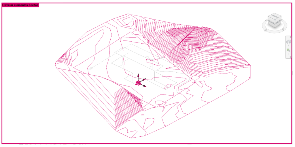
If necessary, you can unhide hidden elements in view. To do this in the View Bar, click on the icon ![]() (Reveal hidden elements) and then all the hidden elements will be displayed in red.
(Reveal hidden elements) and then all the hidden elements will be displayed in red.

Right-click on the element and then Unhide in View > Elements or Category. In the View Control Bar, click on ![]() to exit Reveal Hidden Elements mode and the elements will be visible in the view again.
to exit Reveal Hidden Elements mode and the elements will be visible in the view again.
