Plumbing Systems
The domestic water system is divided into the following systems: Cold Water, Hot Water and Sanitary. In this tutorial an example of creating a Domestic Cold Water system will be shown.
Plumbing Fixtures
Before starting to create a system, it is necessary to insert the plumbing fixtures, such as sinks, waterclosets, bathtubs, and so on. Even though these elements have already been added to the Architecture model, when the architecture is inserted through the Revit link, all its elements are in a single block, which makes it impossible to change. Therefore, it is necessary to insert the family in the plumbing project again, overlapping the architecture family.
Therefore, in the Project Browser, open the “1- Plumbing” view, which corresponds to the Basement plant (if necessary, it is possible to rename it). (image) In the Systems tab, Plumbing & Piping panel, click on the Plumbing Fixture icon.

On the Systems tab, Plumbing & Piping panel, click on the Plumbing Fixture icon.

In the Properties Palette, any device selected by Revit will appear. To change the selected equipment, simply click on the image/description of the element.

The Type Selector will then open, where a list of several families of Revit equipment appears. Use the scroll bar to see all available parts.

For this example, none of the devices that initially appear in the Type Selector list will be used, as new families will be loaded. To do this, after clicking on the Systems tab and the Plumbing Fixture icon, the Modify |Place Plumbing Fixture tab will open, and so click on Load Family.

The Load Family window will open, in which the following path must be accessed: ProgramData/Autodesk/RVT 2022/Libraries/English/Plumbing/MEP/Fixtures. Inside the Fixtures folder, there are several folders named according to the type of equipment. Open the Water Closets folder.

When opening the Water Closets folder, some families of elements of this classification appear. Pressing the CTRL key, select the families: “M_Water Closet – Flush Tank” and “M_Bidet”, and click Open to load them into the project.

Repeat the same process to load the following families:
- Sinks:
- M_Sink – Work
- M_Sink – Service
- Showers:
- M_Shower Stall – Rectangular
Note: In the Properties Palette, duplicate the element and create 4 new ones with the following dimensions:
- 1.60 m x 1.00 m
- 1.30 m x 1.30 m
- 1.45 m x 0.90 m
- 1.20 m x 0.90 m
- Lavatories:
- M_Lavatory – Rectangular
- Bathtubs:
- M_Bath Tub – Maestro
Note: In the Properties Palette, click on Edit Type and change the parameters Bath Tube Width to 1.10 m and Bath Tube Length to 2.50 m.
- Appliances:
- M_Washing Machine
- M_Dishwasher
After loading all the families, you can insert these elements into the view. In the Systems tab, Plumbing & Piping panel, click on the Plumbing Fixture icon. Now in the Properties Palette, in the Type Selector, all the loaded families appear. Select the “Private – 6.1 Lpf” type from the “M_Water Closed – Flush Tank” family.

With the element selected, move the cursor to where you want to insert it. To rotate the object, you can use the spacebar on the keyboard. When the object is positioned, just click on the drawing to insert it.

When clicking on the inserted equipment, the Properties Palette identifies the object and customized changes can be made according to each project. Next to the object, the identifications of the water inlet and outlet connectors appear.

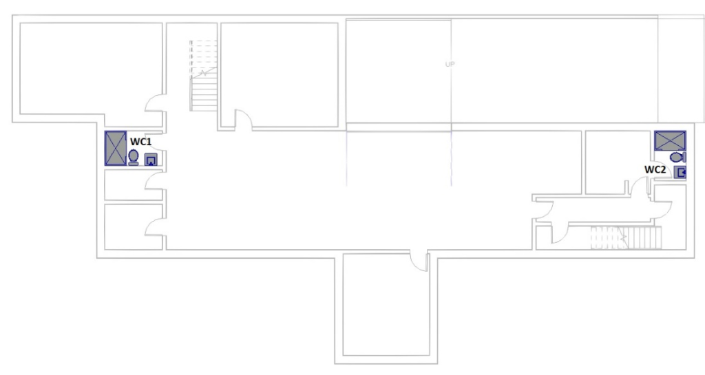
Insert all other elements with the following distribution:
View: 1- Plumbing (Basement floor):
WC 1:
- M_Water Closet – Flush Tank – Private 6.1 Lpf
- M_Lavatory – Rectangular – Private – 560 mmx560 mm
- M_Shower Stall – Rectangular – 1,60 m x 1,00 m – Private
WC 2:
- M_Water Closet – Flush Tank – Private 6.1 Lpf
- M_Lavatory – Rectangular – Private – 560 mm x 560 mm
- M_Shower Stall – Rectangular – 1,45 m x 0,90 m – Private
View: 2 – Plumbing (Ground Floor)
- Bathroom 1:
- M_Water Closet – Flush Tank – Private 6.1 Lpf
- M_Bidet
- M_Bath Tub – Maestro – Private
- M_Lavatory – Rectangular – Private – 560 mm x 560 mm
- M_Shower Stall – Rectangular – 1,30 m x 1,30 m – Private
- Bathroom 2:
- M_Water Closet – Flush Tank – Private 6.1 Lpf
- M_Lavatory – Rectangular – Private – 560 mm x 560 mm
- M_Shower Stall – Rectangular – 1,60 m x 1,00 m – Private
- Bathroom 3:
- M_Water Closet – Flush Tank – Private 6.1 Lpf
- M_Lavatory – Rectangular – Private – 560 mm x 560 mm
- M_Shower Stall – Rectangular – 1,20 m x 0,90 m – Private
- Kitchen:
- M_Sink – Work
- M_Dishwasher
- WC:
- M_Water Closet – Flush Tank – Private 6.1 Lpf
- M_Lavatory – Rectangular – Private – 560 mm x 560 mm
- Laundry Room:
- M_Sink – Service
- Storage:
- M_Washing Machine
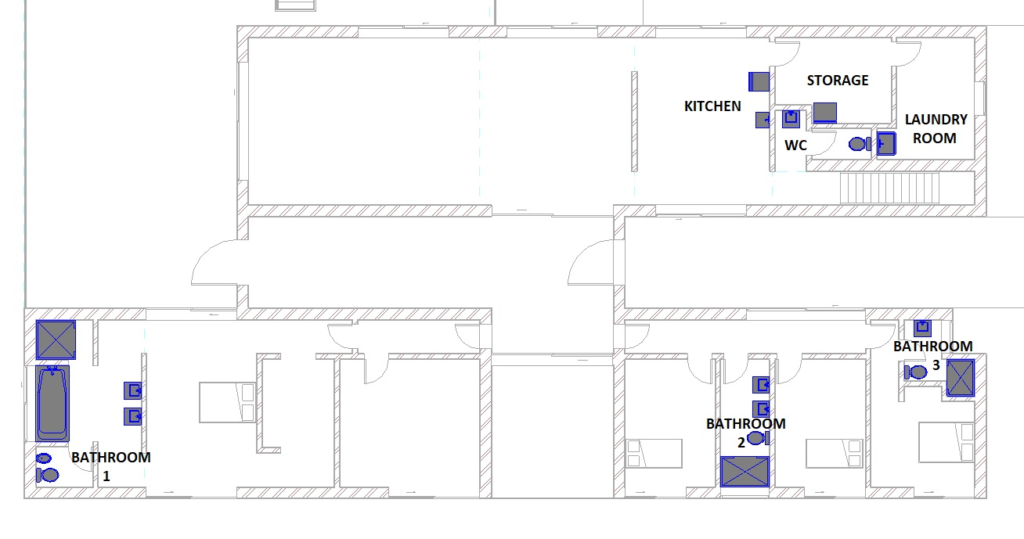
Note: For the element “M_Sink – Work” it is necessary to edit the elevation in relation to the floor. For this, select the element and in the Properties Palette, in the Elevation from level field, fill in the value of 0.80 m.
Create the Domestic Cold Water System
After inserting all the fixtures, it is possible to start creating the Domestic Cold Water layout. To do so, click on one of the inserted plumbing fixtures, and then on the Piping icon on the Modify tab.

The Create Piping System window will appear, in which the Domestic Cold Water option must be selected in System type. In the System name field, the name of the system can be changed (in this case it will be kept), and the option Open System Editor must be checked. After these settings, click on OK.

Select the Add to System tool to add other fixtures to the system.

Move the mouse cursor closer and click on all the fixtures on the Basement and Ground Floor.

After selecting all the devices, click on Finish Edit System ![]() .
.
There are two ways to design the pipes: manually or through automatic solutions generated by Revit, which can be changed after to insert.
To generate it automatically, just click on one of the elements that was added to the system and on the Modify | Plumbing Fixtures, click on the Generate Layout icon.

Revit will then read the elements that have been added to the system, and generate solutions from the arrangement of these elements. The Generate Layout tab will open, where some editing tools appear.

In the Generate Layout bar, it is possible to select the solution type in Solution Type, which can be Network, Perimeter or Intersection, according to the designer’s preferences. In this example, the Network option will be kept. Next to the solution type, there is the number of solutions generated by Revit. In this case, two were generated.

The design model usually establishes the elevations and types of pipes as well as their diameters. However, it may be necessary to specify pipe types and standard elevations for system piping.
Clicking on Settings opens the Pipe Conversion Settings window. In the Main item, in the Pipe Type parameter, select the material “PVC – DWV” and in Offset, define the value of -0.20m, for the pipes to pass below the slab. For the Branch item, make the same changes.

One of the solutions generated by Revit was the one shown in the image below (Solution 1/2 of the Network type). However, it is not the ideal solution, and it is necessary to make some adjustments. As it is an automatically generated solution by the software, there may be differences from one computer to another, and even more solutions.
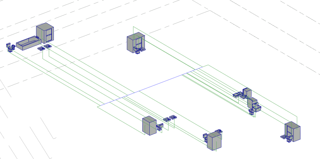
To edit the solution, click on Edit Layout.

With this tool it is possible to drag the inserted pipes and reposition them in the System. In this case, no edits will be made, as adjustments can also be made manually outside the Layout editing.
The diameters of pipes and connections will also be changed later. By definition, all are 15mm in diameter.
Click Finish Layout to complete.

At the end, some errors may appear, one of which may be due to a connection that was left open as shown in the following image.

The above error may be related to another error due to not having space to place accessories.

When showing error windows, the element is highlighted in the drawing for you to check. Now you must proceed, because the errors will be corrected later.
Using the Project Browser, access the “2-Plumbing” floor plan corresponding to the Ground Floor. As the System was inserted -0.20m below the slab of this floor, it will not be visible in this view. To make it visible, in the Properties Palette, in the View Range parameter, click Edit.

The View Range window will then open. In View Depth, change the Level parameter to “Unlimited” and then click OK.

Therefore, the entire system is visible in the view from this floor.
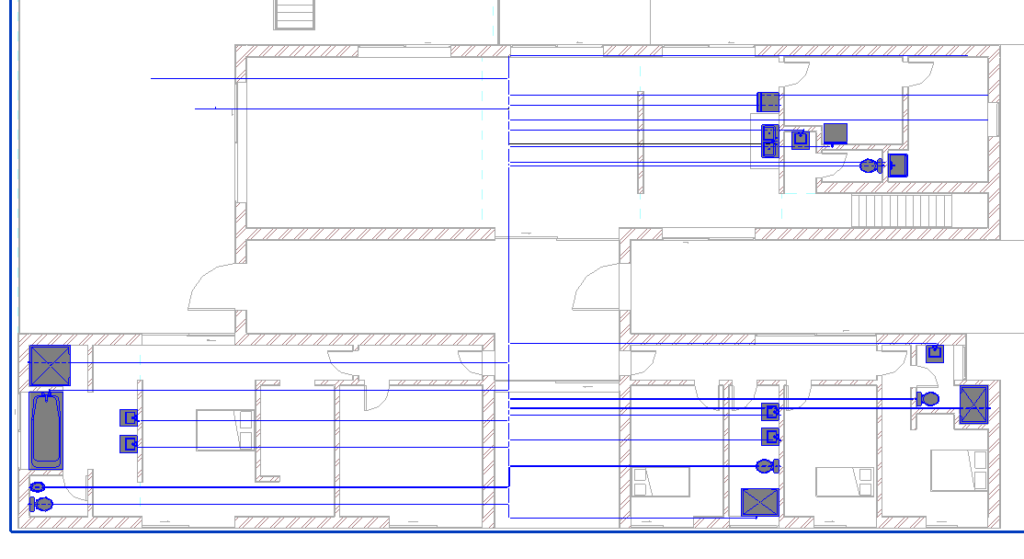
An important tip that helps to improve the visualization of the elements is to decrease the thickness of the contour lines. To do this, click on the Thin Lines tool, located on the Quick Access Toolbar.

Another tip that can help in graphic visualization is to set the Detail Level to the Fine option, and the Visual Style to Realistic or Consistent Color.

From the network layout automatically generated by Revit, manual edits will be made to better adapt it, so that the pipelines are optimized. There is not only one design solution for this hydraulic system, so the network layout varies according to work preferences.
As a demonstrative example, the system region shown in the image below will be edited. It is suggested that the tracing of the other regions also be edited according to preferences.
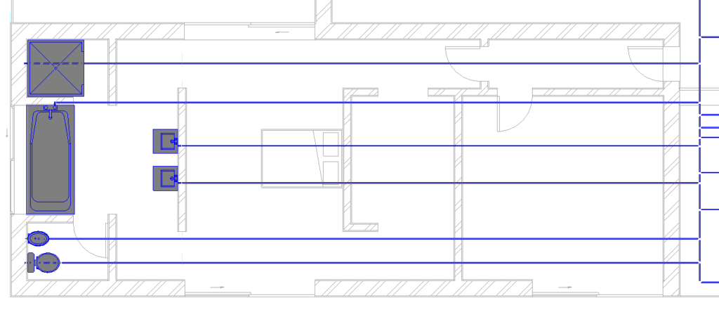
To make your system settings easier to see, you can open elevation views in the Project Browse, and create section views using the Sections tool ![]() on the Quick Access Toolbar.
on the Quick Access Toolbar.
To begin with, the Bidet and Watercloset connections will be excluded in the Bathroom 1, as shown in the following image. To delete an element, just click on it and press the delete key. Check in the 3D view that all connections have been deleted.

To start tracing the network manually, select one of the elements and click on the ![]() “In” icon of the equipment.
“In” icon of the equipment.

Then, a line that represents the piping path appears, which moves according to the movement of the mouse cursor. Observe the temporary dimension and insert 0.10 m into the wall.

In the Systems tab, Plumbing & Piping panel, select the Pipe tool.

In the Properties Palette, verify that the “PVC – DWV” pipe type is selected.

In the options bar, check if the diameter of 15mm is selected.

With this, bring the mouse cursor closer to the end of one of the connections already inserted, and drag to the other one, to connect the two objects.

The pipe that goes under the toilet will also be deleted and a new one will be drawn with the Pipe tool so that it lines up with the pipe at the other end.
You must select the pipe and delete it before creating the new one.

From the 3D view, with the Visual Style in Realistic option, when approaching the mouse to the other end, it is noticed that some connections remained with three outputs.

To remove one of the outputs, just click on the connection and then on the icon ![]() . In this case, as it is a short, straight link, the link will be completely removed.
. In this case, as it is a short, straight link, the link will be completely removed.

It may also be necessary to add one more outlet in some connections, such as the connection that will connect the new pipe to the toilet. To do this, click on the ![]() icon in the desired direction.
icon in the desired direction.
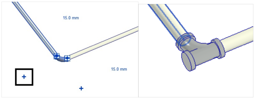
In the Systems tab, select the Pipe tool and click on the new output created for the connection. In the Options Bar, enter the value of -0.20 in Middle Elevation.

Drag the pipe from the connection outlet to the wall of the toilet connection, as shown in the following images.
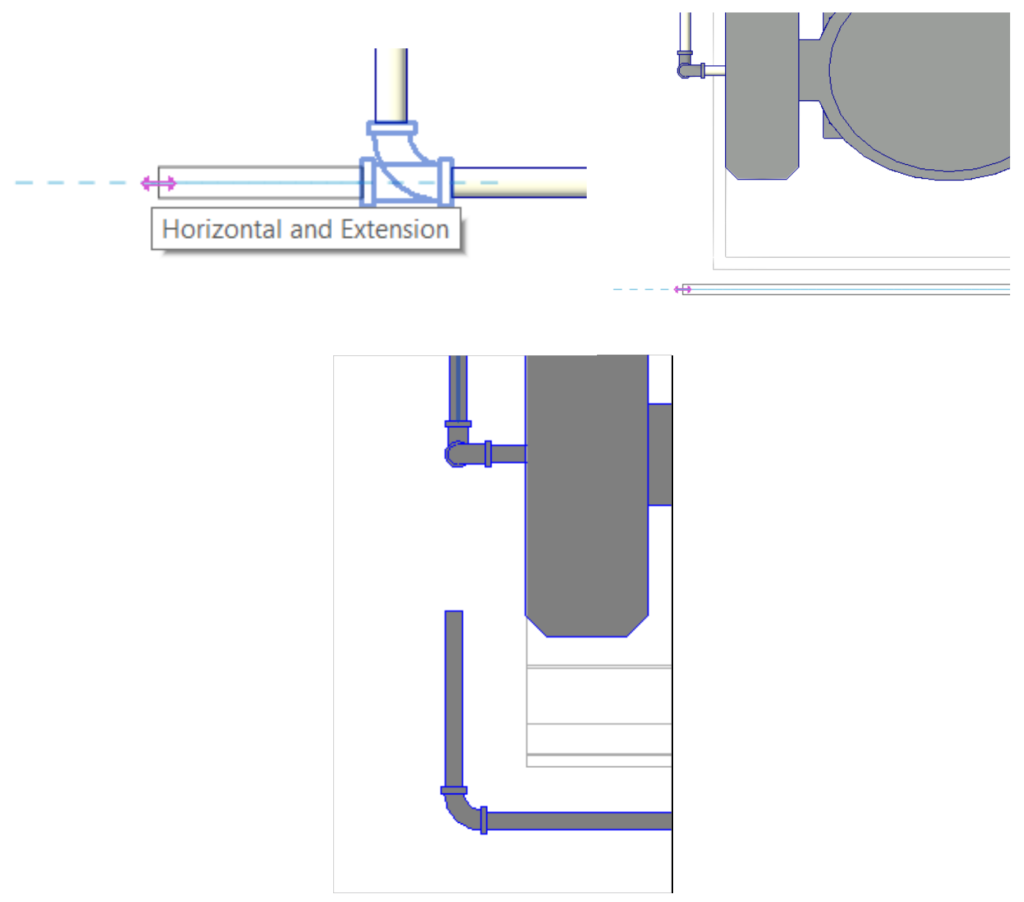
To align the pipes, just select one of them and in the Modify | Pipes select the Move tool ![]() . Select the point in the middle of the new pipe and then the middle point of the toilet pipe.
. Select the point in the middle of the new pipe and then the middle point of the toilet pipe.

You must then select the connection and press the delete key.

To join the pipes, a very useful tool will be used to carry out these processes in Revit, which is the Trim/Extend to Corner tool ![]() . This tool can be used whenever it is necessary to connect pipes. To do this, you must select one of the pipes and on the Modify | Pipe, select the Trim/Extend to Corner tool.
. This tool can be used whenever it is necessary to connect pipes. To do this, you must select one of the pipes and on the Modify | Pipe, select the Trim/Extend to Corner tool.

With the tool selected, just click on the two pipes and the connection will be added automatically.
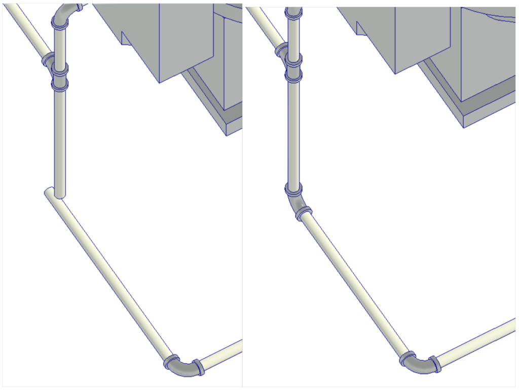
The other equipment will also be connected in a more optimized way, such as the washbasins. This type of washbasin has a diameter of 25 mm for the inlet of cold water. You must change this measurement by clicking on the element and in the Properties Palette click on Edit Type.

The type properties window will appear and the Cold Water Diameter parameter should be altered to 15 mm.

In the same way as was done with the bidet and the toilet, the two sinks will be connected to optimize the piping. Then the lavatory connections must be excluded and then new connections must be created with the “In” tool ![]() on the equipment.
on the equipment.
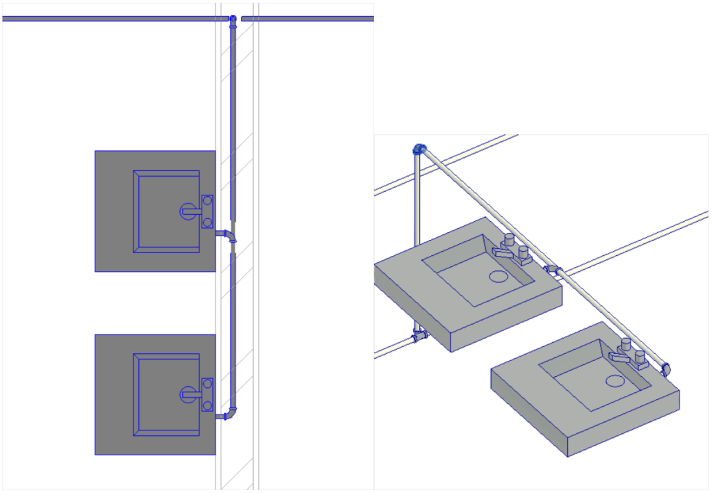
Using the tools mentioned above, connect the shower, bath, wash basins, bidet and toilet in a configuration like the images below.
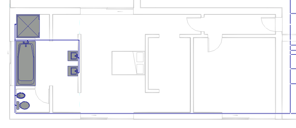
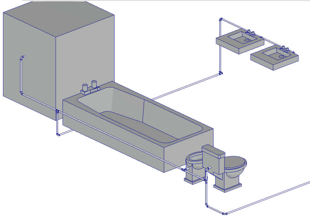
It is recommended to make similar changes in other parts of the system, so that better solutions are created so that it is better distributed.
To assist in designing the system settings, you can open elevation views (Elevations) in the Project Browse, and create section views using the Sections tool ![]() on the Quick Access Toolbar.
on the Quick Access Toolbar.
One of the possible solutions may look like the images below.
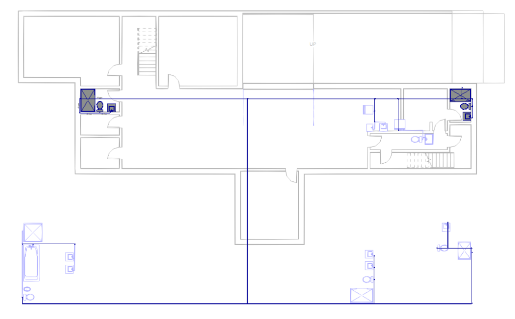
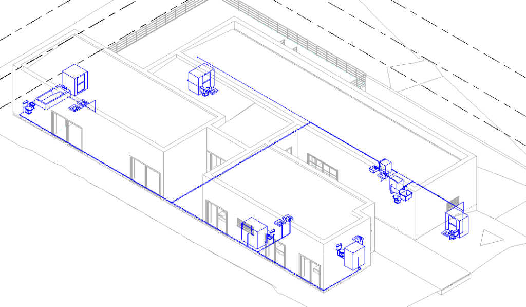
With the Domestic Cold Water system already structured in the project, a pipe must be drawn to connect the system with the point of the public network. In this project, the location of the public network point is not represented, therefore, an approximation will be made.
The point at which the utility connection pipe will connect to the system is circled in Red in the image below.

To start designing the section connecting the public network, open the “2 – Plumbing” view, corresponding to the Ground Floor.
In the Systems tab, Plumbing & Piping panel, select the Pipe tool.

In the Options Bar, change the Diameter parameter to 40mm and Middle Elevation to -0.40m.

In the floor plan, bring the mouse cursor closer to the area circled in red in the previous image and trace a small stretch of pipe up to approximately half of the wall, as shown in the image below.

Delete the existing connection between the two pipes, click the end of the pipe horizontally and drag it to meet the new 40mm pipe.

A connection will be automatically created between the two pipes, with the diameter reducer (from 40 mm to 15 mm) coupled.

To reconnect the pipe in the vertical direction, click on it and drag it until it meets the pipe that was previously connected.

The connections in this area should look like the image below.

You must now drag the pipe to the boundary of the terrain. To do this, open the 3D view and in the view cube click on TOP, to view the drawing from above, as in a plan view. The difference is that in the 3D view it is possible to visualize the boundaries of the terrain.

With this, click on the end of the 40mm pipe and drag it diagonally until it meets the boundary of the terrain.
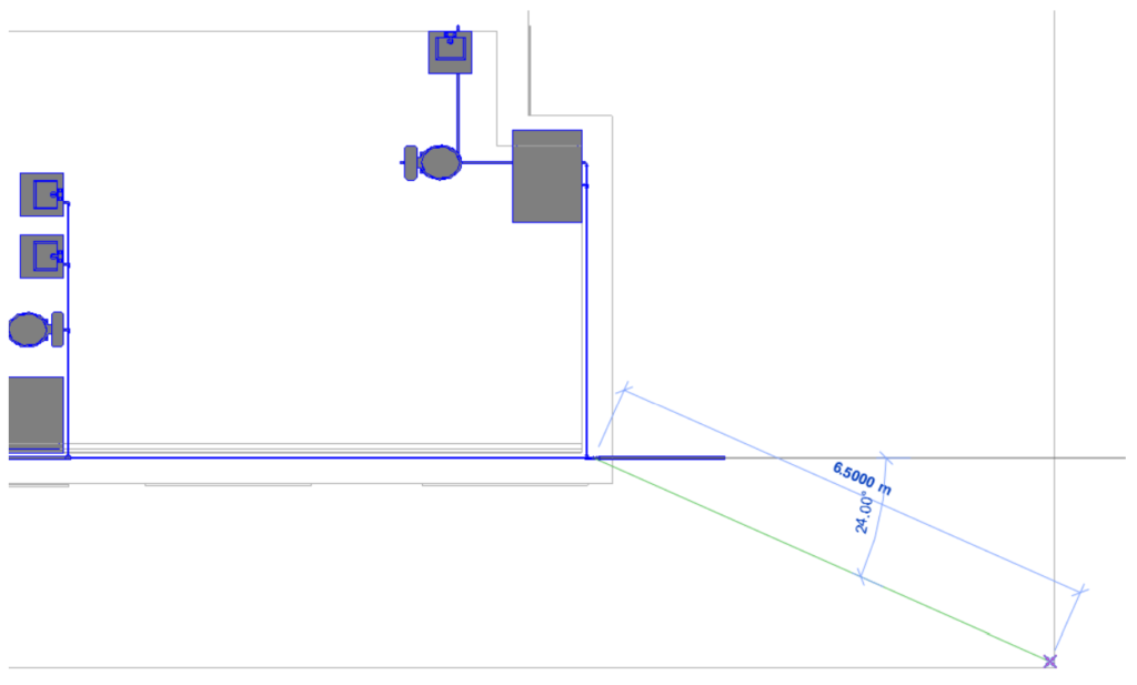
After extending the pipe, click on it to select it. On the Modify | Pipes, Edit panel, select the Cap Open Ends option, to close the unconnected end of this pipe, as the connection to the public network is made by the local water company.

It should look like the image below.

After structuring the entire network, some changes must be made to the diameters and connections in some sections. In the image below, the sections that require a change in diameter are identified. The green sections should be changed to 40mm and the yellow sections to 25mm. The others must be kept with a diameter of 15 mm.
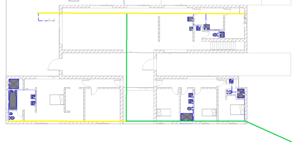
The change is made in a very simple way. Just click on the pipe to be changed and in the Options Bar (Modify Pipe) in the Diameter parameter, select the desired value (25mm or 40mm).

It is very important to verify that when changing the pipe diameter, the connection diameter was changed automatically. If it has not been changed, click on the connection and, in the Options Bar (Modify Pipe Fittings) in the Diameter parameter, select the desired value (25mm or 40mm).

Annotations
To insert annotation elements, such as pipe diameter identifiers, access the Annotate tab, Tag panel, and select the Tag by Category tool.

With the tool selected, move the mouse cursor closer to the element to be identified and the identification text will appear, with the diameter corresponding to the element. Position the text as desired and click on the element to insert the identification.
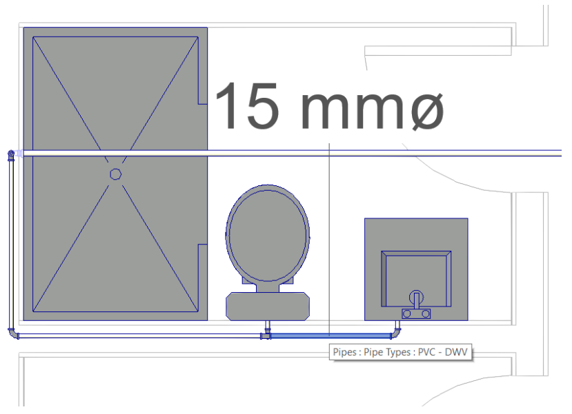
In this case, the text is too large for the scale of the drawing. To change the text size, double click on the text, and then the Modify | Label. Click once on the “Size” text to select it.
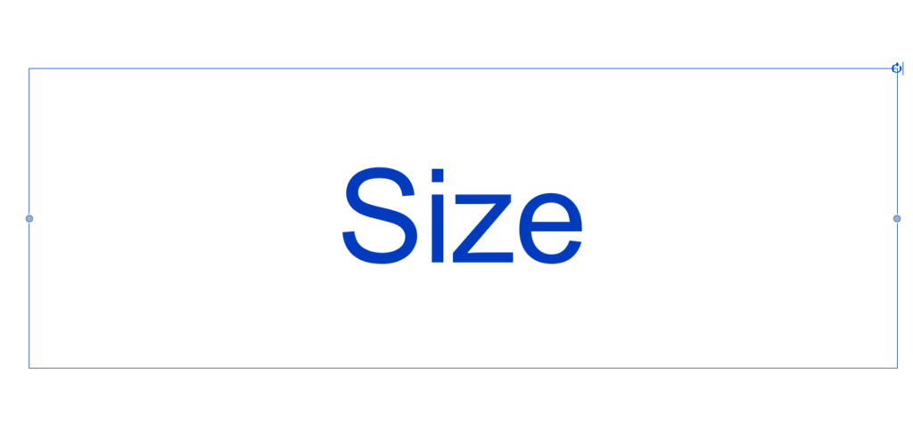
With the text selected, in the Properties Palette click on Edit Type.
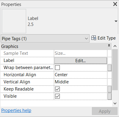
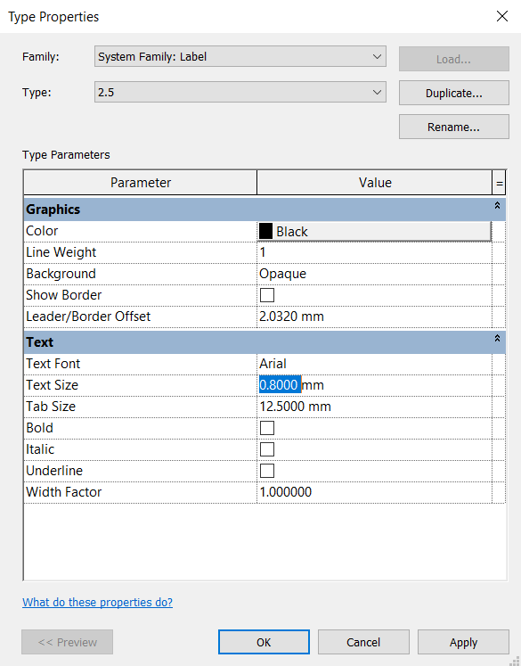
The Type Properties window will open, in which the Text Size parameter must be edited to 0,8 mm.
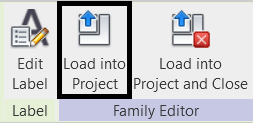
After editing the text size, in the Family Editor panel, click on the Load into Project icon.
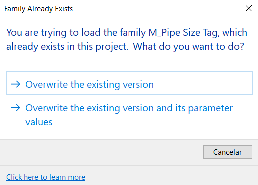
A window will appear warning that the Family already exists. Click on the option “Overwrite the existing version”.
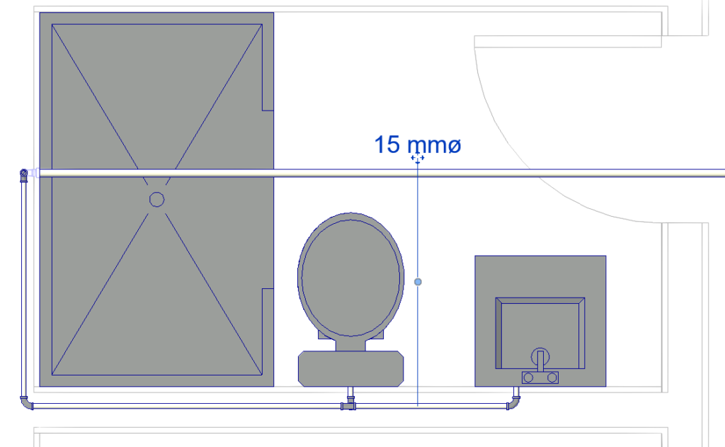
The text is now a more suitable size, if necessary, you can edit it again to make the text even larger or smaller.
To drag the text to the pipe that it represents, click on the![]() icon located just below the text, and drag it to the desired location.
icon located just below the text, and drag it to the desired location.
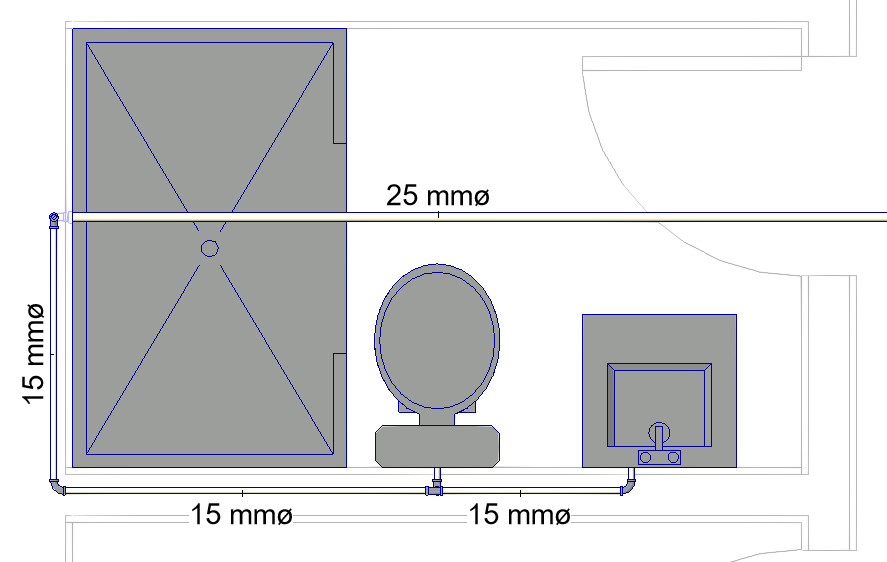
Carry out the same procedure for all the pipes, so that it looks like the following image.
You can also use the Tag All tool, in the Annotate tab.
In the Tag All Not Tagged window, select the Pipe Tags option in the Category column.
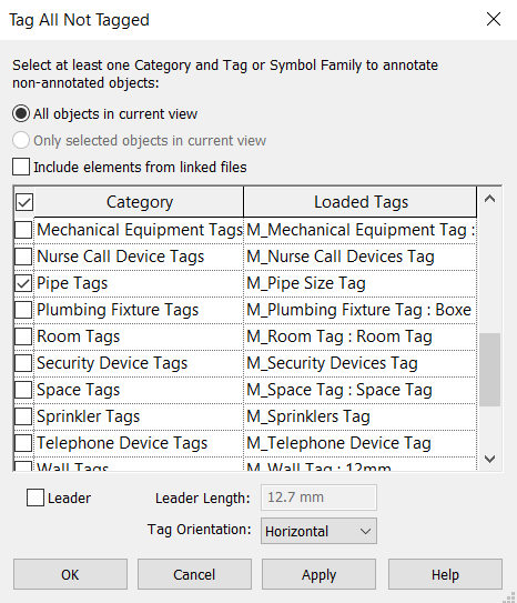
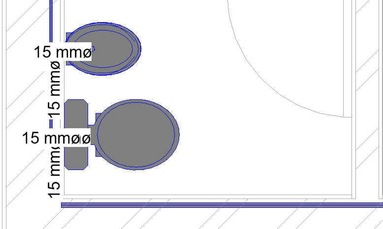
By clicking OK, the identifications are added to all existing pipes in the project. However, many texts end up overlapping and manual adjustments must be made anyway.
Create Schedules
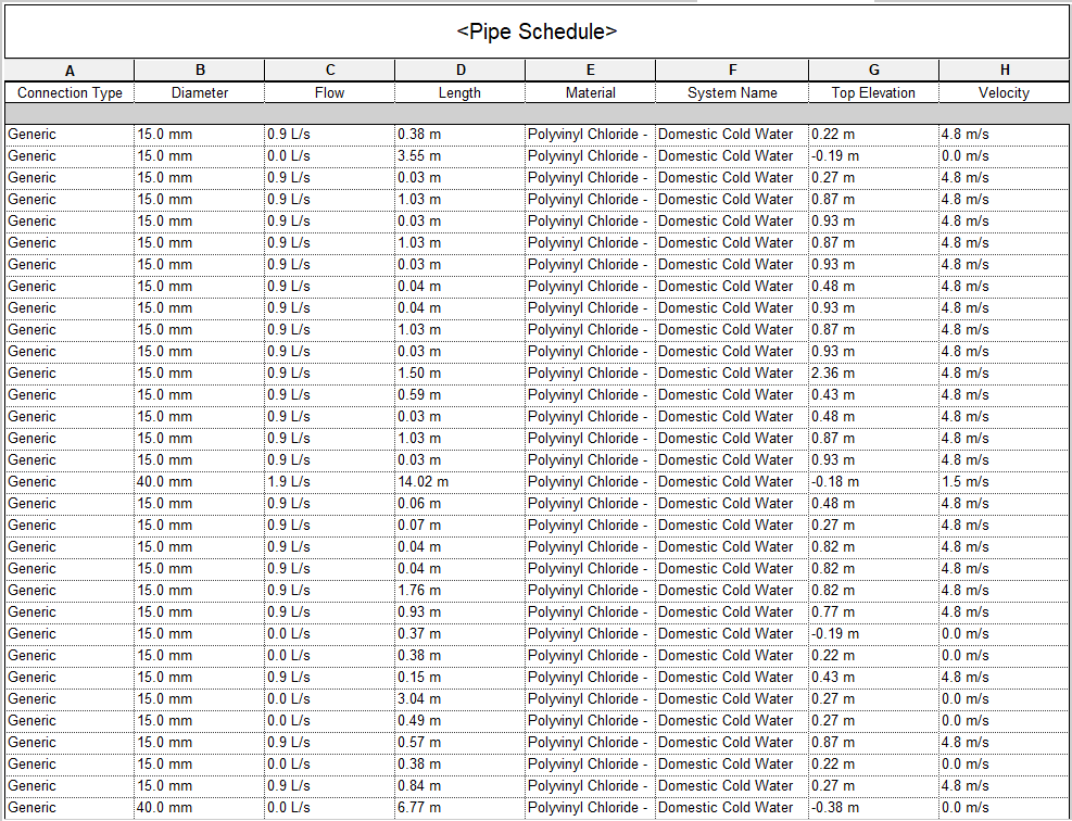
Creating tables for Revit MEP is done in the same way as for Revit Architecture. What changes is the information displayed in each type of table. As an example, a table will be created with information about the pipes.
To start creating a table, in the Project Browser, in Schedules, right-click and then select the “New Schedule/Quantities” option.
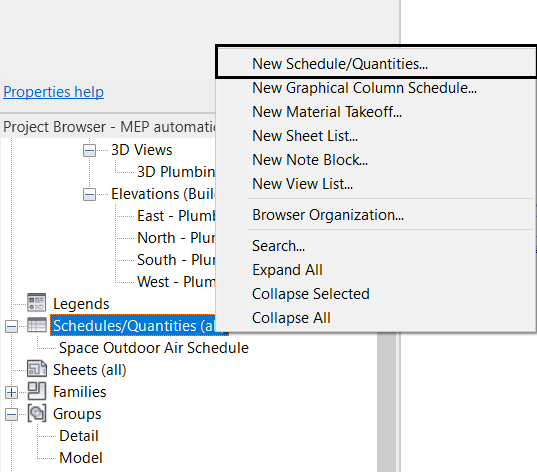
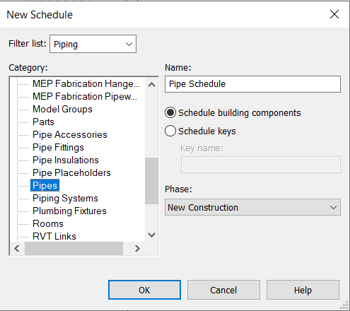
Then in the New Schedule window, under Category, select the Pipes option. In Name, you can change the name of the table. In this case, Pipe Schedule will be kept.
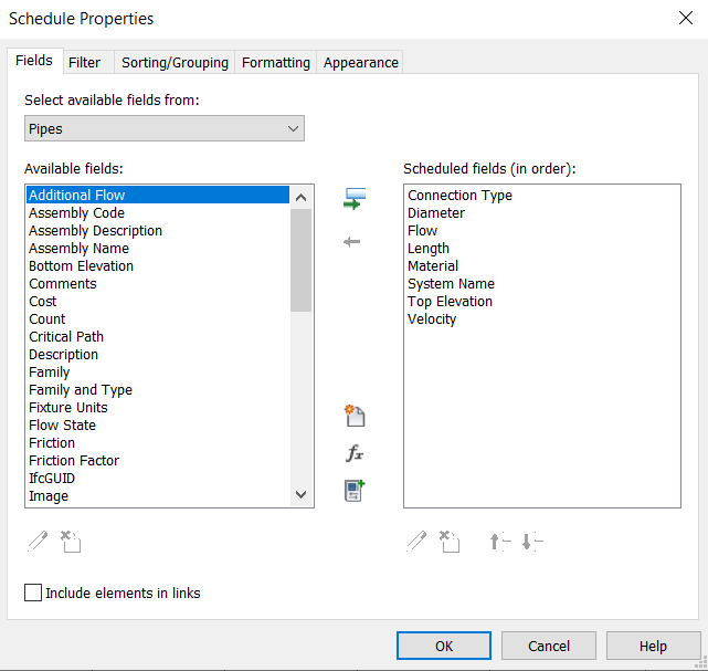
In the Schedule Properties window, in the Fields tab, select the following parameters for the table: Connection Type, Diameter, Flow, Length, Material, System Name, Top Elevation and Velocity.
By clicking OK, the table will be created with all the information that was selected. If any changes are made to the project, the table is automatically updated, and vice versa.
Create Isometric Views
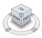
For a better representation of the project, isometric views of the network can be created. To position the drawing in an isometric view, just open the 3D view and click on one of the corners of the cube, as shown in the blue area in the image below.
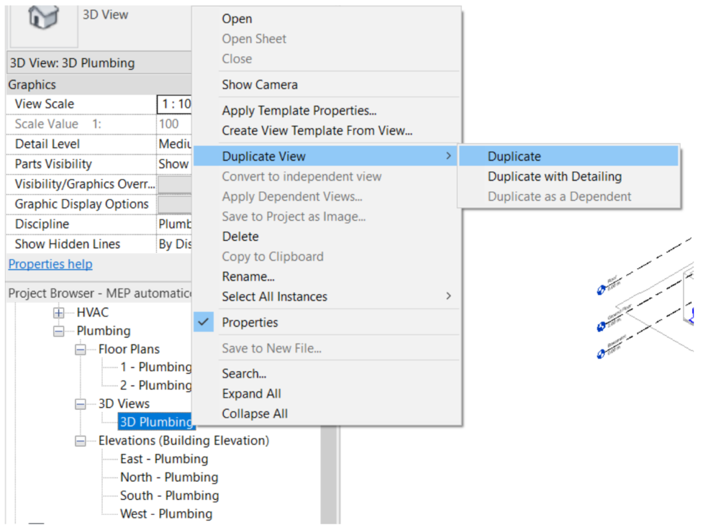
To create a general isometric view of the network, you must first duplicate the 3D view. To do this, in the Project Browser, right-click on the 3D Plumbing view, then on Duplicate View and then on Duplicate. Rename the view to “Isometric Plumbing”.
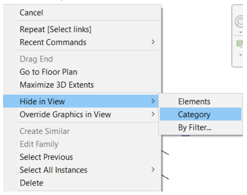
Levels will not be needed in this view, so you can hide them. To do this, click on one of the levels with the right mouse button, click on Hide in View and select the Category option.
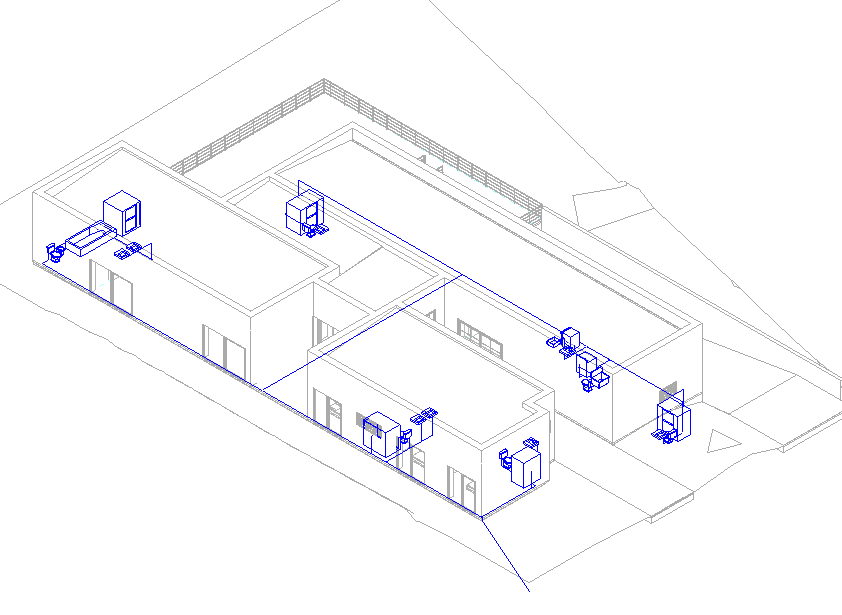
With the isometry positioned according to the image below, the position will be fixed.
To fix the position, in the visualization bar, just click on the ![]() Locked 3D View icon, and select the option Save Orientation and Lock View. The view then cannot be rotated.
Locked 3D View icon, and select the option Save Orientation and Lock View. The view then cannot be rotated.

It is important to define the cropping region of the view, so that when it is inserted into a sheet for printing, it is already adjusted. To do this, click on ![]() Show Crop Region on the visualization bar.
Show Crop Region on the visualization bar.

The rectangle with the clipping region will be displayed. Click on the rectangle and adjust it so that it is very close to the limits of the drawing, as shown in the image below.
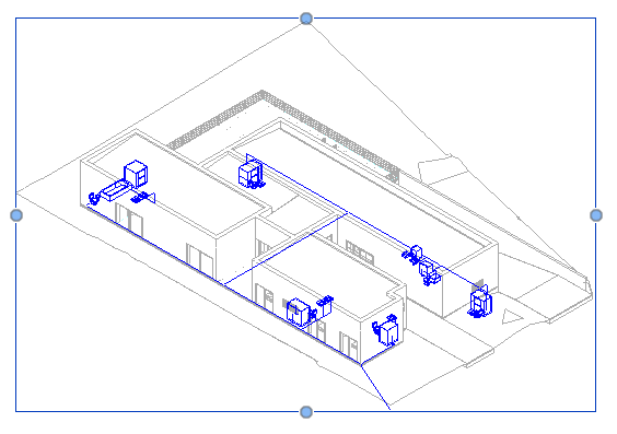
After adjusting the cropping region, on the Preview Bar, select the ![]() Hide Crop Region option to hide the cropping region.
Hide Crop Region option to hide the cropping region.

The general isometric view is created. Now an isometric view of a bathroom will be created. To do this, duplicate the “Isometric Plumbing” view and rename it to “Isometric Plumbing Bathroom”.
With the “Isometric Plumbing Bathroom” view open, click on the ![]() ,Unlock 3D View icon and select the Unlock View option to allow the 3D view to be moved again.
,Unlock 3D View icon and select the Unlock View option to allow the 3D view to be moved again.

Rotate the 3D view through the corners of the visualization cube, until reaching the view as shown in the following image. Once positioned, click on the ![]() Locked 3D View icon again. The red circle represents the environment for which the isometric view will be created.
Locked 3D View icon again. The red circle represents the environment for which the isometric view will be created.
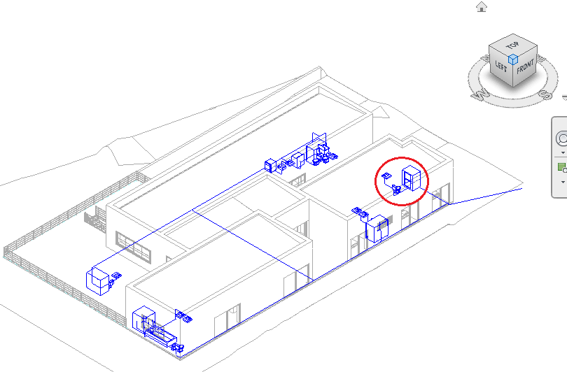
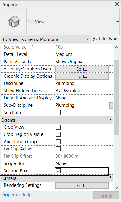
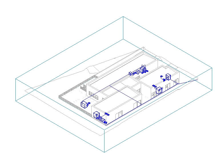
To cut the isometric view only from the desired environment, you can use the Section Box tool. To enable it, just check the Section Box option in the view’s Properties Palette.
A Selection Box will then appear, which you can adjust to crop only the desired environment.
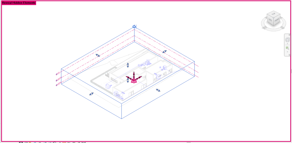
Note: If the Checkbox is not visible, click on ![]() , Reveal Hidden Elements in the visualization bar and then it will appear.
, Reveal Hidden Elements in the visualization bar and then it will appear.
Using the arrows of the Selection Box, you must drag them or click in the direction in which you want to move the Box limit, until you get a result similar to the image below.
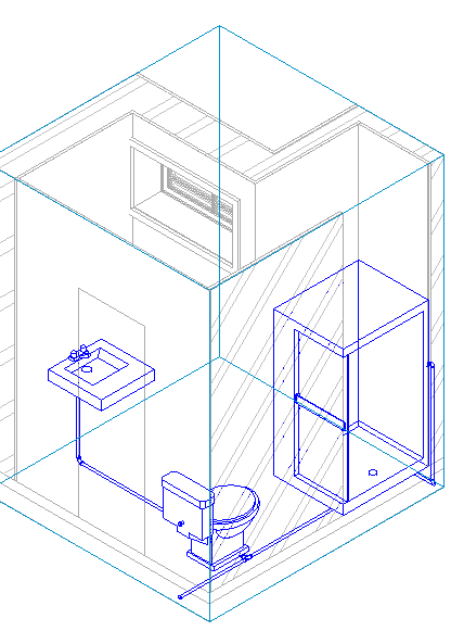
To hide the Selection Box, right-click on it, click on Hide in View and select the Elements option.
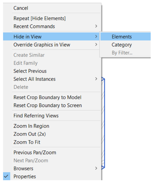
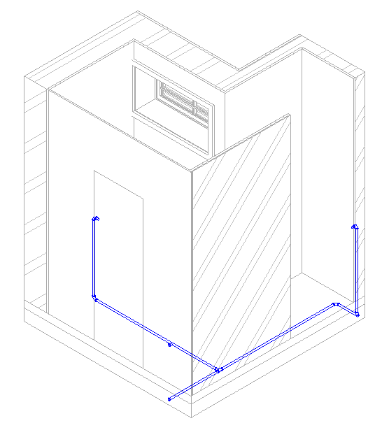
The same can be done for the plumbing fixtures (sink, water closet, shower) if you want only the pipes and connections to appear in the isometric view, as in the image below.
Create Sheets
The creation of sheets for printing is done through exactly the same procedure described in the architectural model tutorial (see item 5.11 of the Revit Architecture tutorial). In this case, following the same instructions, you must create one or more sheets that contain the two plan views and the two isometric views that were created in this tutorial.
