4D and 5D Construction Planning with Navisworks : an Introduction
The construction planning can be detailed using management software such as Navisworks, Vico or Bexel Manager. For that, the complete design of the models, the identification of the activities or tasks and the definition of the necessary resources for each one are mandatory. Any change during the design phase will be easily reproduced in the planning phase elaborated.
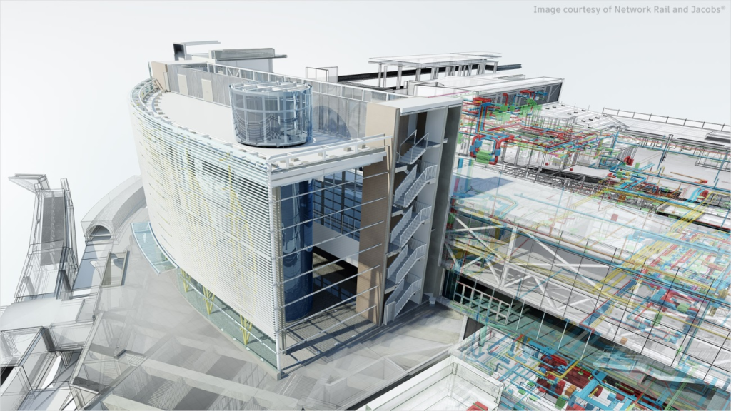
A short explanation of the type of information that can be provided with Navisworks is showed in the next chapters (Figure 2).
An introduction to Navisworks
Navisworks is a review software package to control project outcomes. Navisworks Simulate and Navisworks Manage are tools that enable greater coordination, construction simulation, and whole-project analysis for integrated project review.
Navisworks Simulate is a 3D model review and provides a 5D analysis with project details, quantification and simulation tools. Navisworks Manage enables clash detection and includes advanced coordination, with interference management tools. Navisworks Manage provides a better control project outcome, using tools for coordination and clash detection, 5D analysis, quantification and simulation.
This tutorial will be focused on the Navisworks Manage, with more features. The objective of this Navisworks Manage tutorial is:
- Learning about the use of Navisworks as an open collaboration tool, to built-in clash detection and team management;
- Knowing about how to use this tool to involve everyone in a BIM project and to deliver what is needed by the project team.
Therefore, Navisworks is a project review software package to improve BIM (Building Information Modelling) coordination. It is used for clash detection, simulation, analysis and quantification of activities in construction. The software combines design and construction data into a single model, in a photorealistic rendering, joining data from multiple trades to better control outcomes, identify and solve problems before the construction.
Navisworks can capture material quantities from 2D or 3D designs and export take‑off data to Excel for analysis. The software also allows a planning and timing control (4D) and a costs planning (5D) to be organised using simulation directly from the project model, creating tables with the tasks information. It is also possible to import schedules and cost items from external project management applications.
With Navisworks it is also possible to organize the Facility Management (BIM FM 6D) of the maintenance and operation of a construction, and manager the asset lifecycle (7D).
How to Start
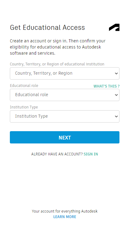
Autodesk provides an educational access to some products and services, which includes the Navisworks software. Students and educators can get free one-year educational access, renewable as long as they remain eligible. It is mandatory to create an account. The useful links for it are:
- To create an account (Figure 3):https://accounts.autodesk.com/register
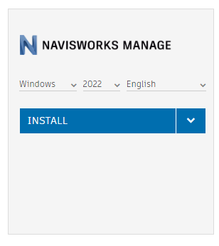
- To download the software (Figure 4, sign in and choose Navisworks): https://www.autodesk.com/education/edu-software
Interface
Figure 5 shows Navisworks workspace and the main menu. Figure 5: Example of Navisworks workspace and main menu.
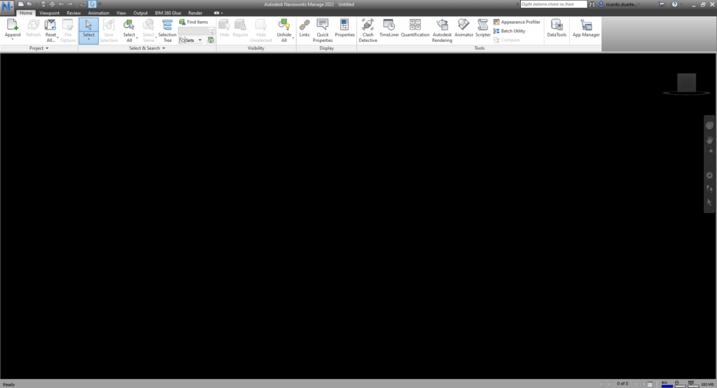
The Ribbon area is located at the top of the workspace and the appearance will change when a different tab is selected. The personalization could cause a different tabs presentation. It is possible to customize and save the display layout, personalizing the interface and the workspace.
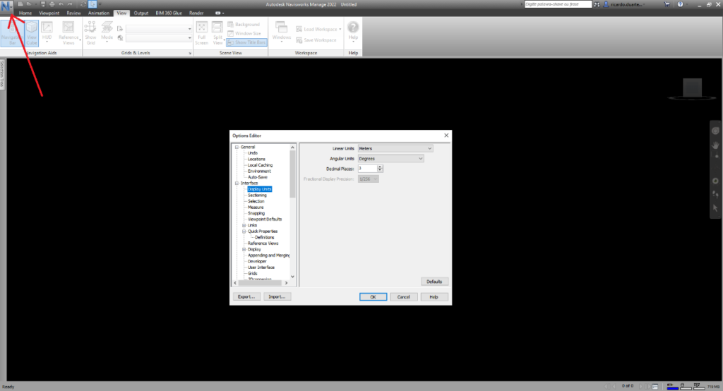
The Options menu is accessed by the Application Button (the one with the big blue N) or clicking with the right button of the mouse and then Global Options, or using the keyboard F12 key. In this menu, it is possible to do the intended customization such as: the file location; the interface options like the unit type or the selection highlight; the file renders; among others (Figure 6).
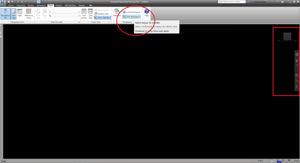
The View menu allows other visualization options and the activation of some toolbars, such as the Navigation bar and the View cube, with UCS orientation, visible in the right part of the workspace (Figure 7).
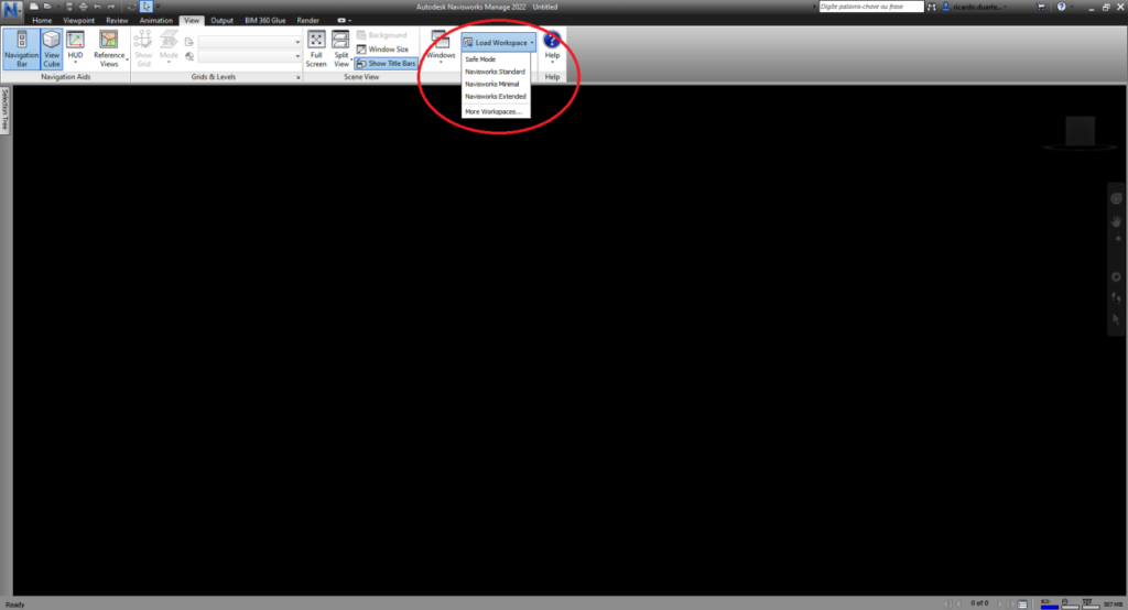
After personalized workspace view customization, it is necessary to save the changes in a different profile. To do that, use the View, Workspace and Save Workspace tab (Figure 7). It is possible to load the different workspaces created (Figure 8).
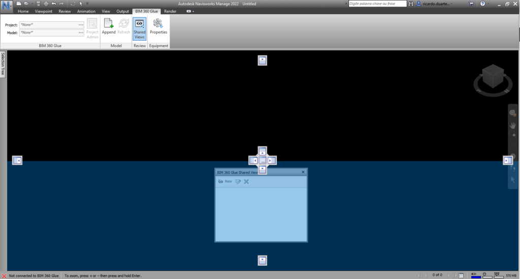
It is also possible to position a box menu by pressing and dragging the box to the intended position. Several arrows represent the position possibilities in the workspace, as illustrated in Figure 9.
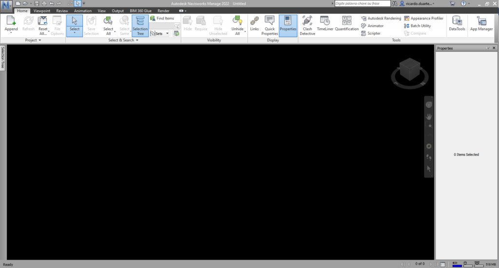
Home Tab
The Home tab (Figure 10) is where the most common commands are located, such as the ones from the Project, Select & Search, Visibility, Display and Tools menus.
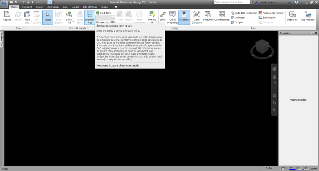
On stopping the selection icon under any command, the command name and a short description of its skills are shown (Figure 11). Figure 11: Example of an instruction in a command
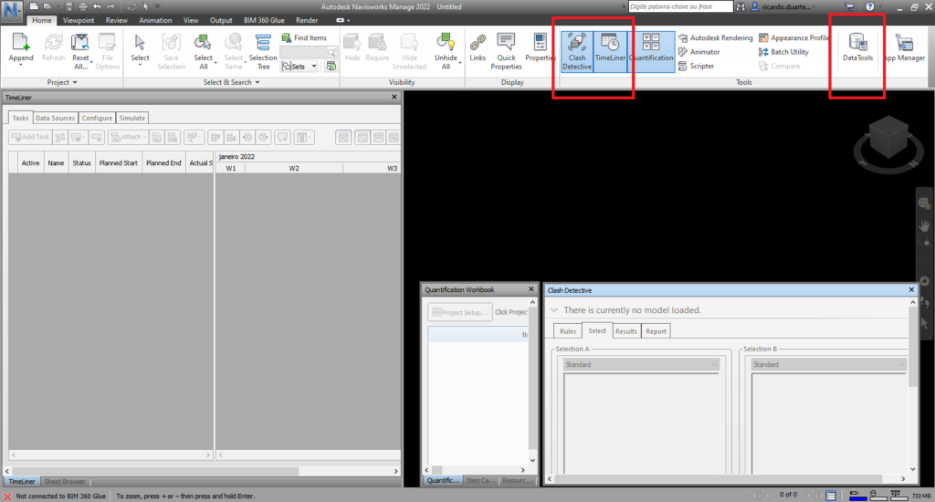
In the Home tab (Figure 12) the functions related to clash detection of the objects could also be found (Clash detective function) and the data information could be loaded (DataTools function).
It is also possible to make a time planning (TimeLiner function) adding tasks with time consumption, definition of the necessary resources to produce each one (work labour, materials and equipment), defining the precedence between them and running the simulation of the whole process. In the planning phase, it is possible to simulate and improved the construction process. Figure 12 illustrates some of the mentioned menus.
Viewpoint Tab
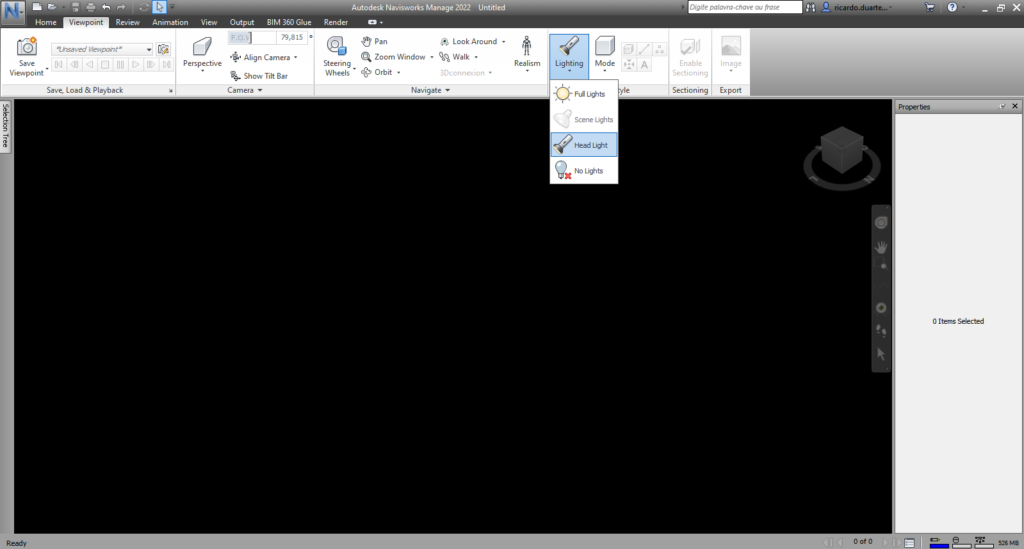
The Viewpoint tab (Figure 13) brings together all the options related with the visualization, such as the Save, Load & Playback, Camera options, Navigate mode, Render Style possibilities, Sectioning and Export menus.
Review Tab
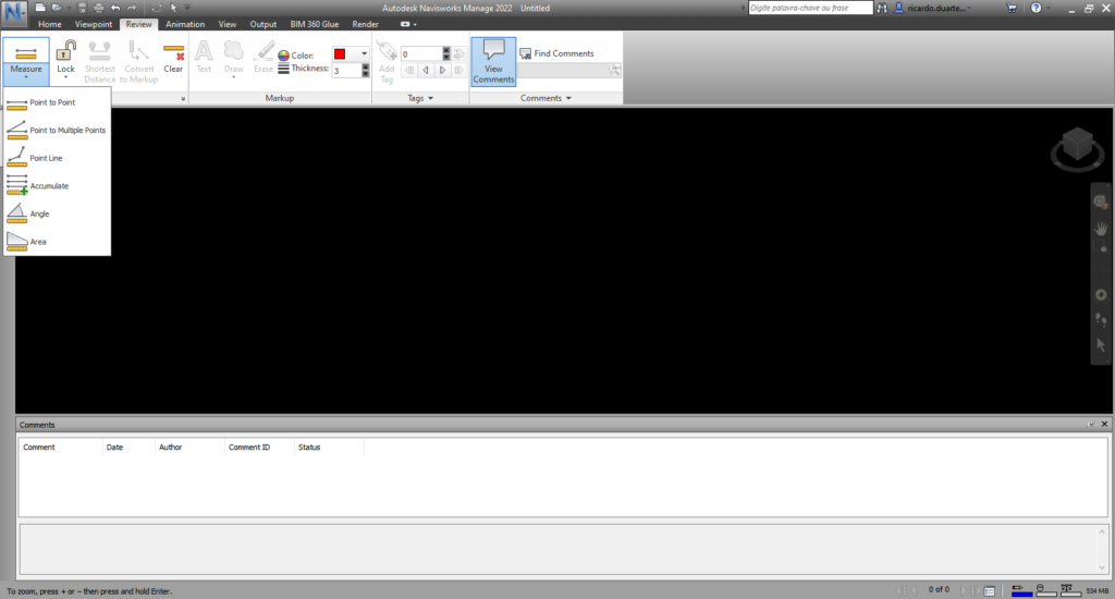
The Review tab (Figure 14) is where all the options related with the review of the project, such as Measure, Markup, Tags and Comments are located.
Animation Tab
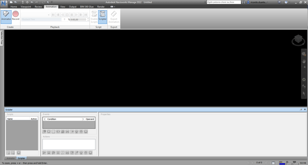
The Animation tab (Figure 15) presents all the parameters related with the videos produced with the model information: Create, Playback, Script and Export.
View Tab
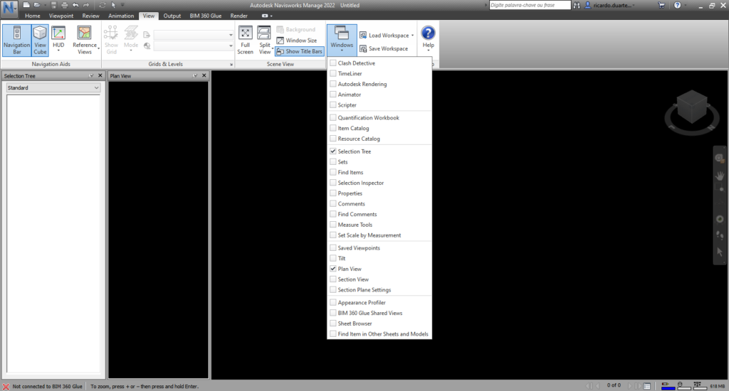
The View tab (Figure 16) presents all the parameters related with the workspace visualization options, as mentioned in the interface point: Navigation Aids, Grids & Levels, Scene View, Workspace and menu Help.
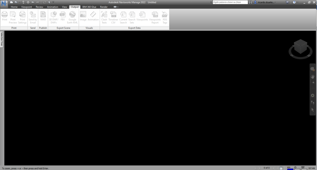
Output Tab
The Output tab (Figure 17) brings together all the parameters related with the output of the model and with the information and data produced: Print, Send, Publish, Export Scene, Visuals and Export Data.
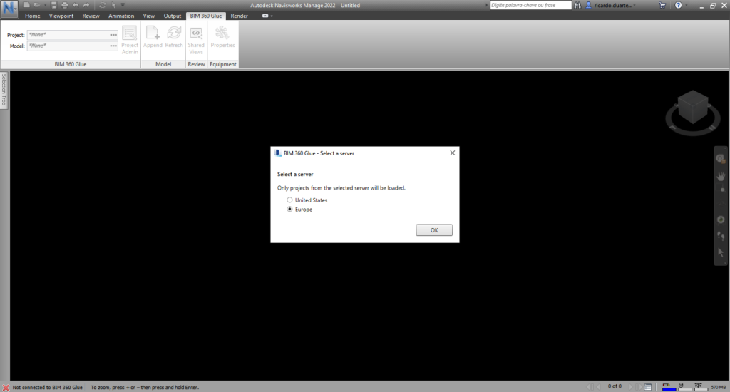
BIM 360 Glue Tab
With an Autodesk account in a BIM 360 server, it is possible to import the project information to the Navisworks model. The BIM 360 Glue tab (Figure 18) allows this task with the menus: BIM 360 Glue, Model, Review and Equipment.
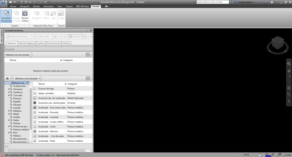
Render Tab
With the Render tab (Figure 19) it is possible to customize the appearance of objects in rendering, for image export, with the functions: System (with Autodesk Rendering options and a Render Gallery), Interactive Ray Trace and Export images menu from the model.