Bim geometric shapes and their modelling
3D modelling concepts have developed from early 2D and 3D CAD representations which were mainly composed of 2D or 3D lines. The first 3D wireframe models were an extension of 2D drafting where 3D lines were manually drawn to create a 3D wireframe model. This could be used for visualisation and to create orthogonal views. These early 3D wireframe models had no mass properties and it was not possible to add features such as holes (Figure 1) .
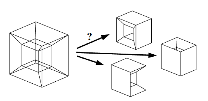
Spatial geometry shapes are an integral part of BIM. In order to move from drawing in traditional CAD platforms to the modelling of specific construction objects, it is natural that the objects could be drawn as realistically as possible. If the drawing does not provide any information about the layout of the geometric shape, it may not be possible to obtain it in 2D CAD drawings. Especially when it comes to the height of buildings. When working in a 3D CAD environment, these complexities are largely solved. It is important for the practitioner to understand how the relationships between geometric shapes, internal parts of software and information in both 3D CAD and BIM modelling applications are constructed. Figure 2 shows an example of the principal spatial geometric shapes and their processing forms.
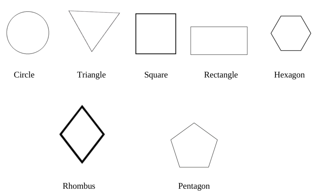
Geometric shapes: circle, triangle, square, rectangle, hexagon, rhombus, pentagon, and so on.
Spatial shapes: cube, cone, rectangular parallelepiped, quadrilateral pyramid, triangular prism, ball, roll, triangular pyramid, sphere, torah.
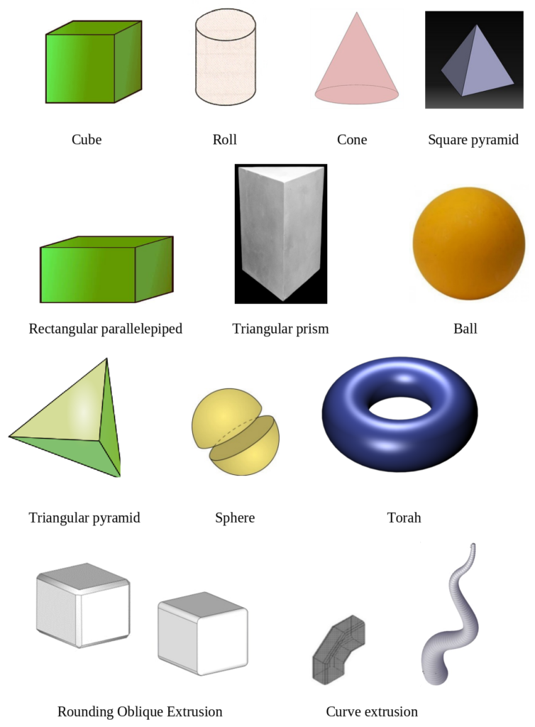
Figure 2 – Spatial geometric shapes and their processing forms.
Regarding the quality of the model, geometric accuracy of the elements is a very important aspect, so it is necessary to take care to prevent intersections and errors in the geometric models.
Even specialized software cannot understand and decide for itself what quantities of geometric shape elements need to be estimated in an automated project budgeting. For instance, if the elements of reinforced concrete columns overlap or intersect with wall structures, the project implementation cost will be calculated higher than planned.
Thus, BIM managers or BIM coordinators must ensure the quality of the design of the geometric shapes. This prevent uncoordinated solutions from changing during the construction process and allow an accurate calculation of the quantities of items.
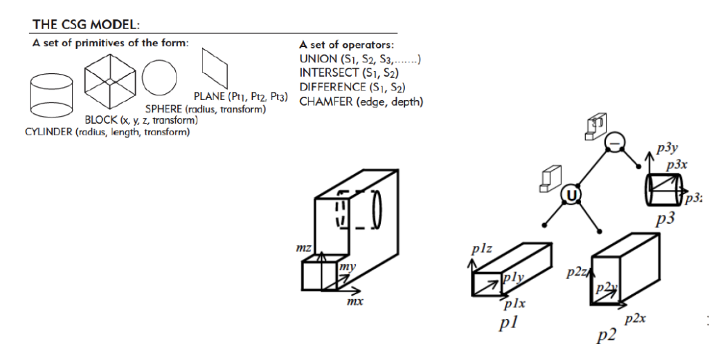
Two important advancements in 3D CAD modelling introduced in the 1970s and 1980s were the concepts Constructive Solid Geometry (CSG) and Boundary Representation (B-rep). CSG uses solid primitive shapes to represent objects (Figure 3). This approach is more powerful than previous wireframe approaches as solid objects can be used to calculate various physical properties such as volume, density, weight and mass. CSG also allows solid primitive shapes to be combined using Boolean operations such as union, subtract and intersect to create more complicated shapes (Dore and Murphy, 2017).
Alternatively, Boundary Representation (B-rep) represents objects by describing their faces, edges, vertices and topology. B-rep also includes operations such as extrude, sweep and revolve which can be used to create 3D shapes from 2D outlines (Figure 4). Many CAD software platforms incorporate both B-rep and CSG modelling concepts to provide greater flexibility for modelling complex objects (Dore and Murphy, 2017).
The B-rep method conveyed shapes as closed, formed from individual surfaces in contact with each other. The shape itself was defined by a set of rules to ensure that contacting surfaces completely closed the volume inside. This set of rules determined how those surfaces should merge and connect, how to navigate, their orientation in the environment and how their continuity should be ensured. In addition to these spatial volume creation functions, functions for extruding shapes along an axis or curve have also been developed.

Figure 4 – Boundary Representation (B-rep)
B-rep’s edge representation method for describing geometry models is dominant in CAD and BIM software.
One of the first and up-to-date formats for storing B-rep geometry is the STEP format. The number of possible geometry modification transactions is greater than in models. The B-rep model shall only be stored as a final result and the geometry design travel shall not be retained. Modern 3D CAD systems allow detailed parametric modelling with B-rep models through the mathematical description of curves or even a typical B-splines description of the NURBS (Non uniform rational B-Splines). The B-rep model has two types of information: geometry and topology. Geometric information is the mathematical definition of curves, surfaces required to form a geospatial body.
Topological information allows to link geometric elements to each other. There are also two types of entities in B-rep models:
• Geometric subjects – Volume, Surface, Curve, Point;
• Topological subjects – Solid, Face, Edge, Vertex.
The differences between these concepts are presented in Table 1 and illustrated in Figure 5.
Table 1. Difference between geometric and topological objects.
| Geometric object | Topological object | What is different |
| Volume | Solid | Volume is usually considered to be an object created not from primitives, that is, extruded according to a curve, surface, etc., and a solid body is usually composed of geometric shapes. |
| Surface | Face | Surface may be defined by curves which vary in shape in space and Face refers to a flat surface consisting of only straight sides, e.g. the top of the cylinder is not considered to be a Face but a Surface, unless it is segmented as a polygon. |
| Curve | Edge | A Curve is defined by points and a function that controls its position in space. Edge is considered to be a line segment between two Vertices. |
| Point | Vertex | A Point describes a specific point in space with its specific coordinate according to the applicable coordinate system. A Vertex is just a reference to that point. For example, multiple tangent polygons that have individual vertices, but can identify the same point. |
The application and alternation of these operations allows the creation of several geometric spatial volumes. At the same time, functions emerged that made it possible to merge individual volumes or cut one spatial volume from another. These actions are defined as Boolean operation. One of the first application for such modelling is the modelling of machine parts, which often consisted of typical volume primitives and join / cut operations.
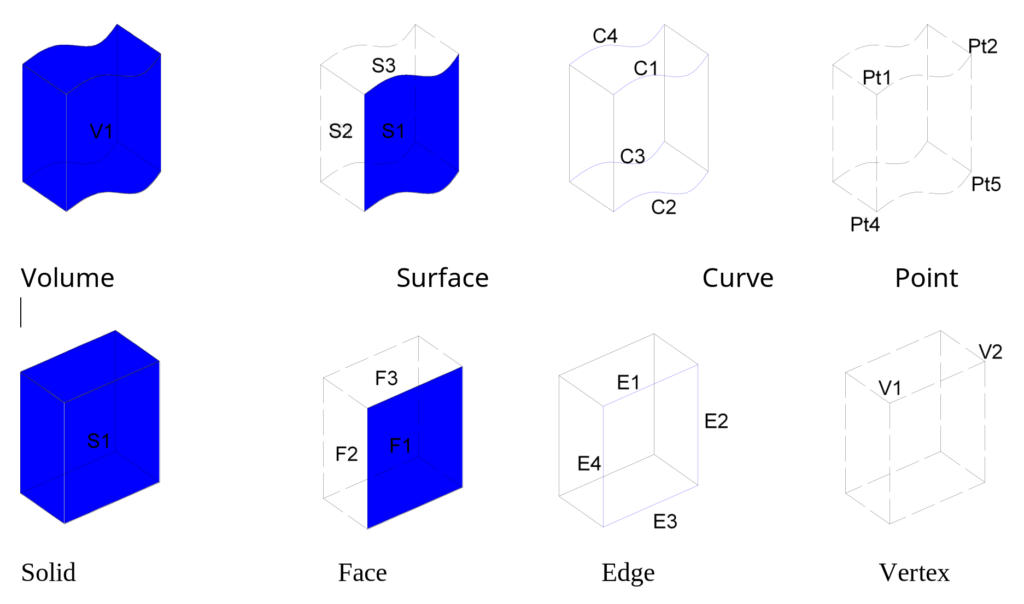
Figure 5 – Entities forming geometry and their topological equivalents.
Because these two methods had different but very important properties, solution to combine the two emerged. This allowed the creation of spatial geometric models by the CSG method, leaving B-rep to deal with the evaluation of the modeled primitives and visual representation. This principle of operation has survived to the present day, which gives CAD and BIM systems their power to quickly and accurately create geometry, edit it and display it on computer screens. In other words, CSG applies to modelling and work, and B-rep applies to rendering, intersection checking, and other non-editing operations. It should also be noted that it was this combination that paved the way for parametric modelling.
Spatial volume modelling and corresponding CAD systems have always been characterized by a very high demand for computer computing power. Even current existing systems are not always able to handle complex 3D models. With the development of computers and the growing progress of the construction sector, the era of spatial modelling began.
3D shapes represented with CSG and B-rep methods exist only as graphic entities and do not have intelligence (Ibrahim and krawczyk, 2004). The next evolutionary stage in 3D modelling was the introduction of parametric and feature-based modelling which introduced a certain amount of intelligence into model elements.
The next evolutionary stage in 3D modelling was the introduction of parametric and feature-based modelling which introduced a certain amount of intelligence into model elements. Feature-based modelling is an object orientated approach where in addition to geometry, objects contain information about the objects role (e.g. door, wall, window etc.) and how an object relates to other objects. Feature-based modelling allows operations such as creating holes, fillets and chamfers to be associated with objects. This could include a window automatically cutting a hole when placed in a wall or intersecting walls connecting and joining correctly. Feature-based modelling enables objects to interact with other objects correctly and automatically in a spatial environment (Leeuwen and Wagter, 1997).
