Hermitage Case Study
The data capture of a large element is based on the continuous photographic taking by superimposition from different distances and angles, in order to obtain information.
The use of drones greatly expands the value of the data documented by photographic capture because thanks to the drone is possible first of all to access places where the technician can not reach, can save heights and document elements with greater proximity as the cornices or overhangs present on the facades of buildings also capture another large series of elements were hidden to the eye such as roofs.
The height plays a relevant role not only when it comes to reach or access but also when it comes to photographic documentation in general, thanks to the height that a drone can reach can perform a three-dimensional mapping of the terrain documented physical relief of the environment or elevations, floors and roofs of the structures that are within the area of flight and capture.
Data capture: Data capture is done using drone for aerial shots and SLR camera for terrestrial shots.
Drone: The flight missions of the drone, are assisted by the Pix4Dcapture application, which allows us to establish a link between the mobile device connected to the controller and the drone.
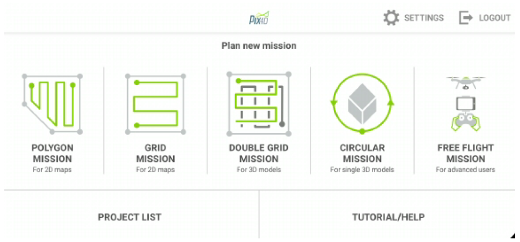
For the realization of this exercise we have decided to make 2 flights over the captured building.
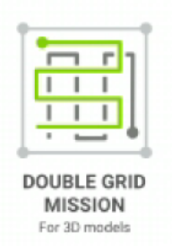
1 – A Double Grid flight mission to document the entire roof and the environment in which it is located, with a 45º inclination to document relief elements, a mission carried out at a height of 30m.
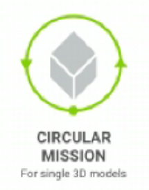
2 – The second flight mission that is performed with the drone is the circular flight which is performed at a height of 20 meters; the circular path makes the axis on which the drone orbits the building itself so we can obtain photographic data in diagonal perspective obtaining data from both the roof and the elevations.
Camera: Photographs are taken with a reflex camera to obtain more information about the elevations, humidities, cracks and peeling of the elevations in order to better analyze the pathologies of the structure. Parallel tours to the elevations are carried out on 4 sides of the building, obtaining a total of 69 photographs.
Software installation: The Reality Capture software is installed from its website https://www.capturingreality.com/DownloadNow It is necessary to register to use it, because although the information processing and editing is free, if you want to download the photogrammetric project, you must pay a small fee. It is possible to register using Google Account, Facebook or your Epic Games account if you have one.
Reality Capture Processing: After the field shots, we proceed to the office or cabinet work for which we will have to manage in the photogrammetric processing exercise about 69 terrestrial photographs and 198 aerial photographs being in total about 267 photographs.
Beginning with the settings, it is advisable to set the Image Overlap to Medium or High if you have not taken a considerable number of photographs, due to the amount of data processed both aerial and terrestrial.
Once the parameters have been adjusted, we proceed to the orientation of the photographs and the search for the first search of homologous points in the form of a scattered point cloud by selecting the option 

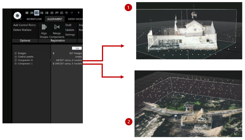
After processing, we can see that the set of photographs has not been processed in the same “Component” but they have been divided into 2 components, this is due to the origin of the photographs. The program has divided and processed in 2 different components the terrestrial photographs and in another component the aerial photographs, so we obtain 2 different components formed by 2 different point clouds that correspond to the terrestrial session and the aerial session.
 As we can see in the photographs above, in the terrestrial component only the elevations can be seen without documenting the roofs or external information of the terrain or the surroundings.
 On the other hand, in the second photograph we can see a view of the point cloud with data from the roofs of the building, elevations and the adjoining terrain; so we can see the interest of combining both photographic shots that complement each other perfectly.
So, to join both components we need control points taken manually, these control points will serve us to transmit the information to the program that the selected points in both aerial and terrestrial photographs are the same point or element, so when restarting the process once the points are obtained the program will synthesize the information and join both components into one.
To do this, start by selecting the section in the top bar and then divide the screen layout into 4 segments using the icon that mimics the result, found in the top bar in the left corner.

This action will divide the layout screen into 4 parts, then we select the screens one by one with the and assign to each of them a corresponding command, to assign to each of the screens a colour.
- Screen 1: CTRL+1.

- Screen 2: CTRL+2.

- Screen 3: CTRL+3.

- Screen 4: CTRL+4.

We proceed to drag from the images panel of the left table photographs to each of the 4 cells of the layout, being able to make a tour of all the photographs of the project, when we find a common element in numerous photographs click on it in each of the boxes, you can use the Zoom to have more precision, it is very important to perform this process accurately so it has to be an element captured in several photographs easy to select and not represented in a blurry way. Once you select the element in the 4 images you can continue looking for the same element in the following images by dragging the next 4 images to each of the cells of the layout and repeating the process consecutively.
The greater the number of photographs that record a point, the more accurately it will be represented, likewise, the greater the number of points added, the more accurately the project will be aligned.
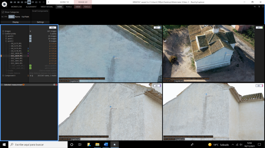
Once the points have been documented in both aerial and terrestrial photographs, repeat the alignment process and click on the button:

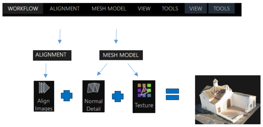
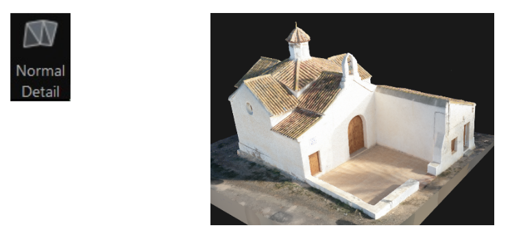
After obtaining the point cloud, we continue with the mesh processing, therefore, we access to the section ![]() and select the normal detail option, if the alignment has been satisfactory, the reconstruction of the polygonal mesh does not require the settings to be retouched.
and select the normal detail option, if the alignment has been satisfactory, the reconstruction of the polygonal mesh does not require the settings to be retouched.
SCHEME
